I have been been a little quiet in here lately, but I have been working on this more. Specifically, I have been drawing up the fully detailed wiring diagram for the new harness and a pin-board to get length estimates with. Although I do not plan to make a physical pin-board since enough of the original harness will remain intact to keep things properly sized, I will probably install it into the chassis after removing all of the tape and cleaning it so that I can route all of the new stuff in-place to get the lengths exactly right. The pin-board drawing is more for determining quantities of wire to buy.
PDF links are the full-size drawings of the "thumbnail" images.
For the pin-board drawing, I started out by measuring out everything on a 100% stock harness. Dimensions probably vary a bit since these things are all 30 years old and varying amounts of tugging/abuse have been applied, but everything is likely within 1cm of where it should be.
OEM E30 M42 Harness Dimensions
http://www.e30tuner.com/assist/e36x/PinBoard-OEM.pdf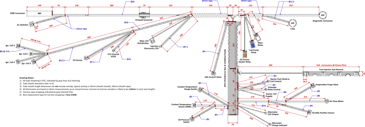
I have already posted this elsewhere, but here are the OEM E30 M42 wiring diagram and the modified one I am using currently with my MAF conversion & WBO2 on stock Motronic, in full color:
http://www.e30tuner.com/assist/m42wireharness/EngineHarness_M42B18_E30_318iS_OEM.pdfhttp://www.e30tuner.com/assist/m42wireharness/EngineHarness_MM2100.pdfAnyway, it took a fair bit of work to figure out exactly how I wanted to add & route all of the new stuff for the Link ECU. A primary goal was to have a single wire loom coming from the ECU, which means that I will need to void my warranty and solder some jumper wires inside the thing from the "extra" I/O pins on the G4X ECU and unused pins on the main 88 pin connector. Also, while it has a built-in MAP sensor, I do not want to have a vacuum line running through the firewall (both from a SMOG/visual standpoint, and just for cleanliness). So that means that I will be using a Bosch MAP+IAT sensor, mounted directly in the plenum of the intake manifold.
The other thing I had to think about a lot was the fuel injector wiring. The stock setup has a pluggable sub-harness for the injectors. The ONLY reason I can see for this is to make engine removal/installation simpler at the factory. Removing the injector harness requires removal of the upper intake manifold. In my experience, the M42 is much more easily removed/installed without the upper manifold anyway, and (*FINGERS CROSSED*) I don't anticipate removing the engine again anytime soon. With the "mess under the intake" mod, the upper manifold can be removed without messing with the TB, and is a 10 minute job. So, with that said, the fuel injector wiring will run through the little side-port in the rubber umbilical that the ICV wires previously exited from. This is the most direct route for the injectors. The ICV, MAP & fuel P&T sensor wiring will exit where the fuel injector connector used to be (with a 3D printed PEEK filler/adapter for the grommet). It just makes more sense that way.
New stuff which I will be routing through the wire box under the intake manifold:
- Oil pressure + temperature (mounted in oil filter housing where the pressure switch was, with some custom machining to adapt the existing M12x1.5 hole to take the M10x1 sensor)
- Fuel pressure + temperature (will machine an inline tee adapter for the fuel feed line)
- Manifold pressure + temperature (no long vacuum lines to mess with, and nice direct measurements in the plenum)
- Dual knock sensors (mounted to the existing knock sensor bosses on the block)
- M50 ICV (still not quite sure where or how I will mount it...it is a fair bit longer than the M42 ICV and has larger in/outlet ports)
As previously mentioned, I will be adding 4 wheel speed inputs. On top of that, I will be adding connections to the brake switch, and adding a clutch switch. The ECU supports "flat shifting" and since that only requires one additional wire to be run from the clutch switch, why not? If I am going to expend all of this effort, then I am going to take advantage of every possible feature. The only thing I do NOT plan to do is convert to electronic throttle...that is just way too much work for minimal gain in anything, at least for now.
That is a lot of typing. Here are the drawings of the new & improved pin-board & wire diagrams. These are certainly a bit busier than the OEM ones! I shudder to think about what these would look like on a modern BMW engine.
http://www.e30tuner.com/assist/e36x/PinBoard-E36X-Prelim.pdfhttp://www.e30tuner.com/assist/e36x/EngineHarness_E36X-Prelim.pdf

If you are thinking "damn, this guy has a bit of OCD...he's only making one of these" then you are at least partially correct. Regardless of whether or not I actually have OCD, graphic design has always been a little side passion of mine, although I am really mostly into technical drawings rather than "art." More than that though, I have found that with wiring projects, the Seven P's of Life apply very heavily. Proper Prior Planning Prevents Piss Poor Performance. When I was younger and far less patient, wiring/electrical work was done much more ad-hoc and always ended up messy, buggy and ultimately causing many headaches. At least for me, fully documenting & detailing a project like this means that the experience will be a lot more enjoyable and likely to work on the first try. And of course, my E30 brethren might find this useful. If documenting some of this work inspires someone else to do this (or something similar) then it is all worth it.
Anyway, I got the drawings done enough today that I can finish my list of materials and start ordering wire, connectors and other supplies. The next big task will be to completely tear-down the spare donor harness and clean it up. There is an unreasonable amount of "goo" all over it from the decaying harness tape, which will probably require me to go through at least 500mL of isopropyl alcohol. I have already been through this once when fully rebuilding/modding the harness that is in the car now, and it is a pretty tedious task!
Can you guys recommend some sources of good molded hoses? I will need some 90 degree elbows and whatnot, probably with a pretty tight radius, to make the M50 ICV work. I'll also need some reducers and other things like that. The M5x vacuum hoses for the ICV might work if I hack them up, but they seem to be needlessly expensive.
Lastly, what are your thoughts on the following. The opening in the rubber umbilical guide where the ICV wire exits is sized for a ~4.5mm OD wire sheath. In order to run the 5x16ga wires for fully sequential injection, I need to use a sheath that is ~9mm OD. I have test-fitted this, and physically I can get it to run through there. However, I have some concern that over time the rubber may split open, being stretched to ~2X its original circumference. Information I have found online indicates that vulcanized rubber can be stretched to well past 3X its original length without issues, but if anyone here happens to know a lot about rubber compounds I'd appreciate thoughts on whether I should reconsider this. It really is the ideal spot to route the injector wiring through!
