Ok boys & girls, time for another update. I mocked-up a prototype adapter plate (it is usable, but there are some design changes I want to make now that I have the part in my hands).
My employer was throwing away some old manufacturing fixtures a couple of years ago, and I offered to take them off of their hands instead. These things were made with 120lbs (each!) of machined aluminum, in various bar & plate forms. So, needless to say, I have had close to 100lbs of aluminum plate laying around for years, waiting for me to do something with it. Anyway, I found a suitable piece & needed to trim it down for the adapter plate. I started with a bandsaw, but it was way too slow.
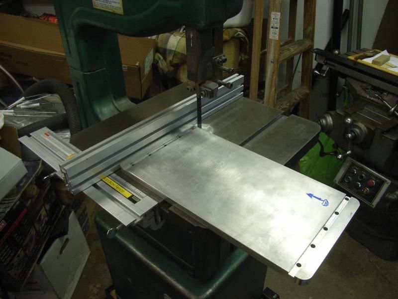
So I stuck it in a vise and milled it into shape!
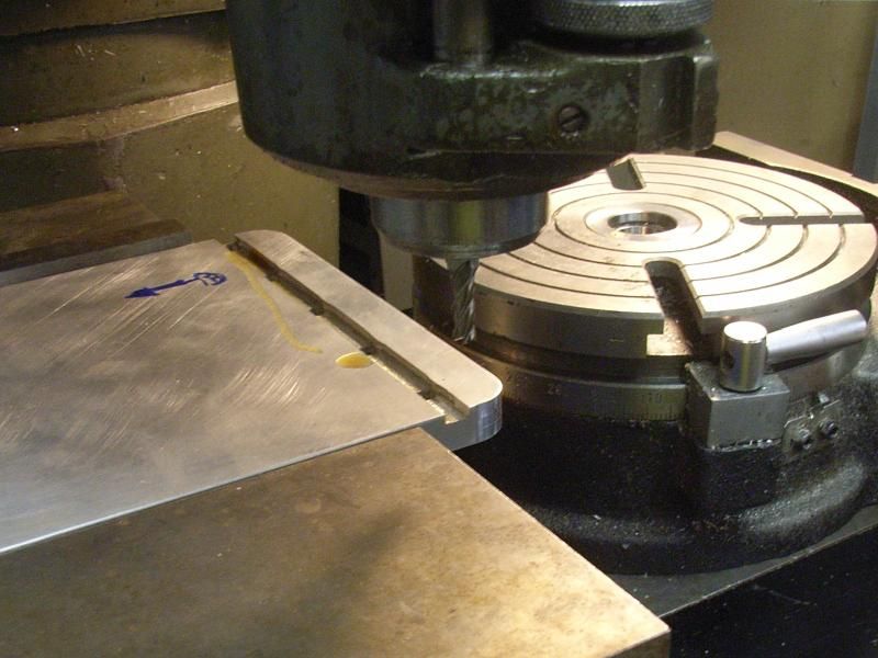
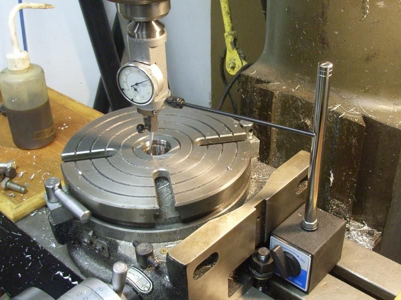
Next, I needed to get the rotary table centered. This little dial gadget is super handy! Put it in a 1/4" collet, set the spindle to ~100RPM and adjust the X/Y position until the needle stops wobbling.
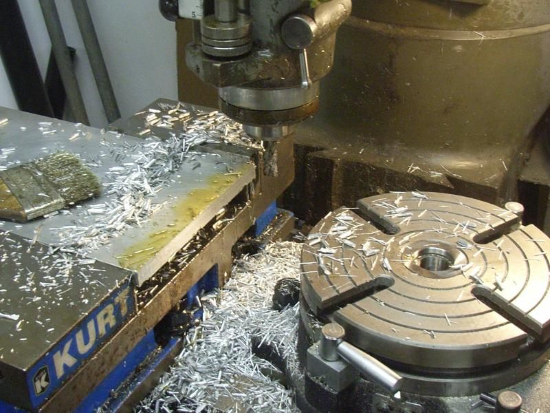
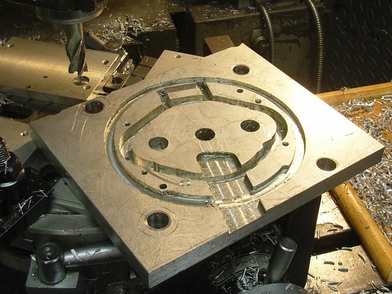
I got down to business & made all of the back-side cuts. The 3 larger holes in the row were used to set the center position of the work piece so that all of the various rounds could be cut.
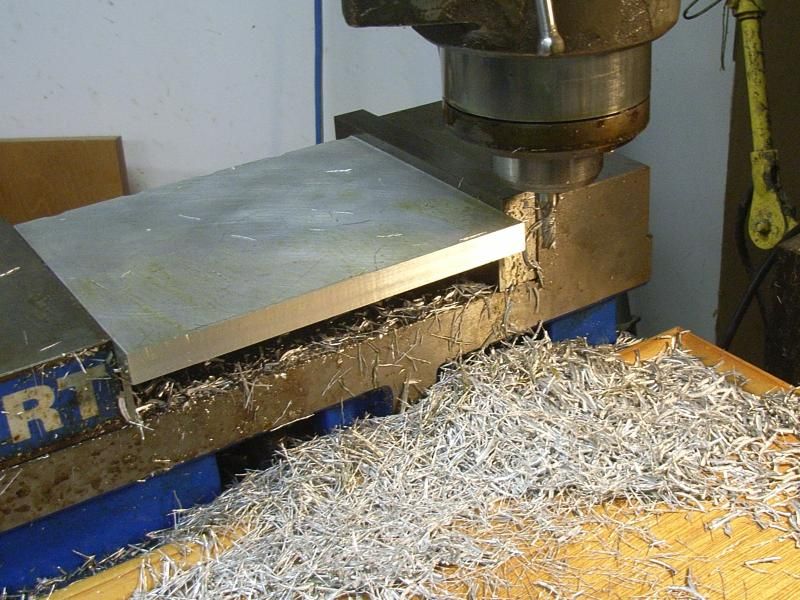
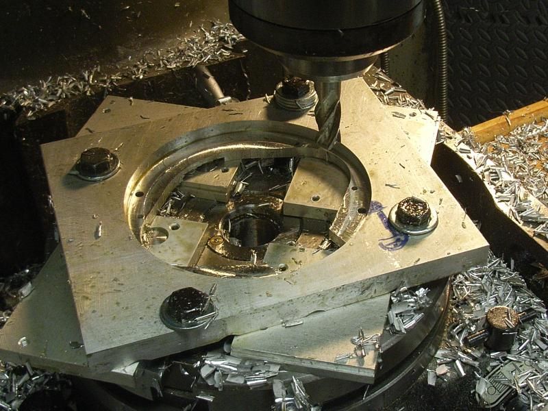
Here it is, half-way done with the top-side operations. It didn't take much work since I had cut the inner profile perimeter already. Once I knocked ~.6" off of the inside, the middle bit fell right out!
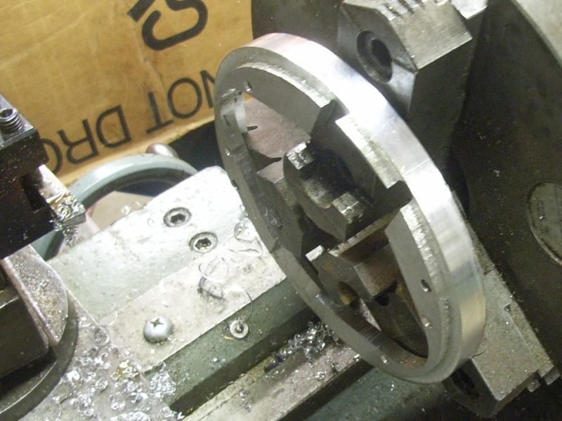
The crappiest part of this was cutting the outer perimeter. It involved a delicate dance of milling, stopping to remove one bolt, milling, stopping to put it back, etc x 4. By the end, it was not holding the part securely. So, I cut my losses (no pun) and chucked it up on the lathe to clean it up.
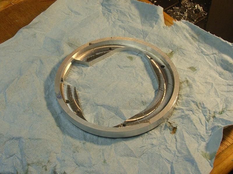
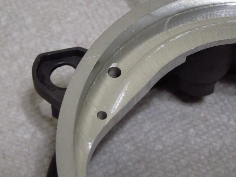
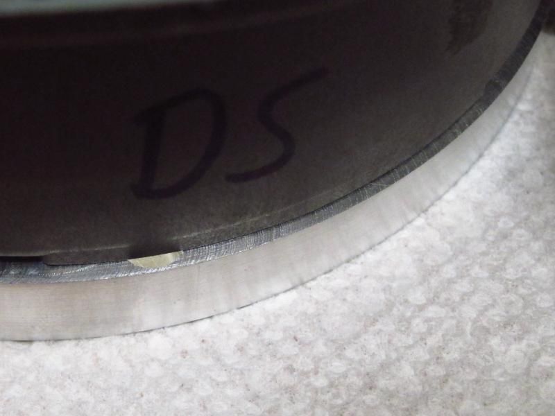
All cleaned up, although it got taken down to 4.99" instead of the intended 5". Whatever, it is a prototype.
So, here is one. Whoever says you NEED a CNC mill is telling lies. With some effort, you can design most parts to be made manually. Hell, the digital position readout unit on the mill crapped out last year, and I ran this part without any electronic positioning at all. As long as you know what "backlash" is, you'll be fine. All you need is the ability to add & subtract in your head, and a decent dimensioned drawing. Oh, and calipers are a good idea, too!
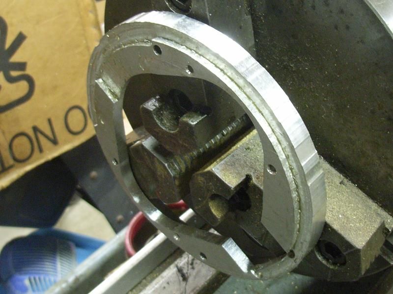
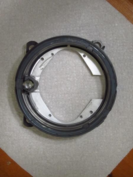
So, how did it fit?
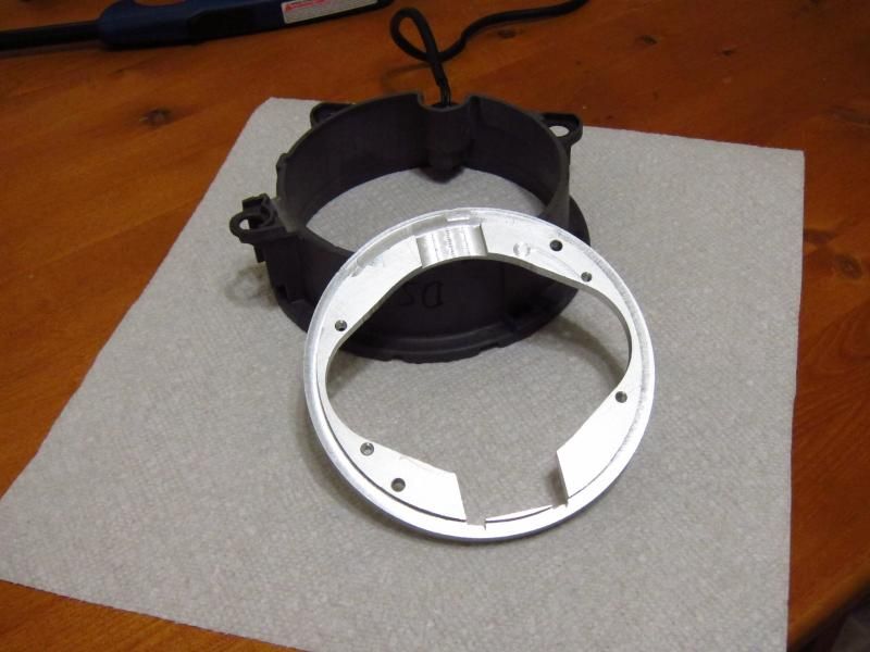
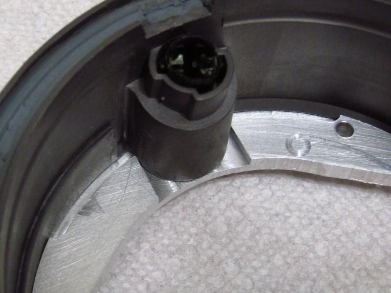
Well, it fit almost perfectly. Snug, with zero slop (much to my surprise). It does rotate ~0.5 degree thanks to an "oops" in the cutout for the city light, but radially there is no movement at all.
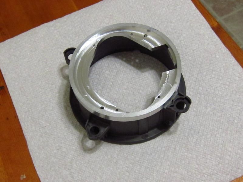
I will be taking the lessons learned here & making two more that should come out better. I did most cuts in a single pass, which is always a recipe for rough milled surfaces.
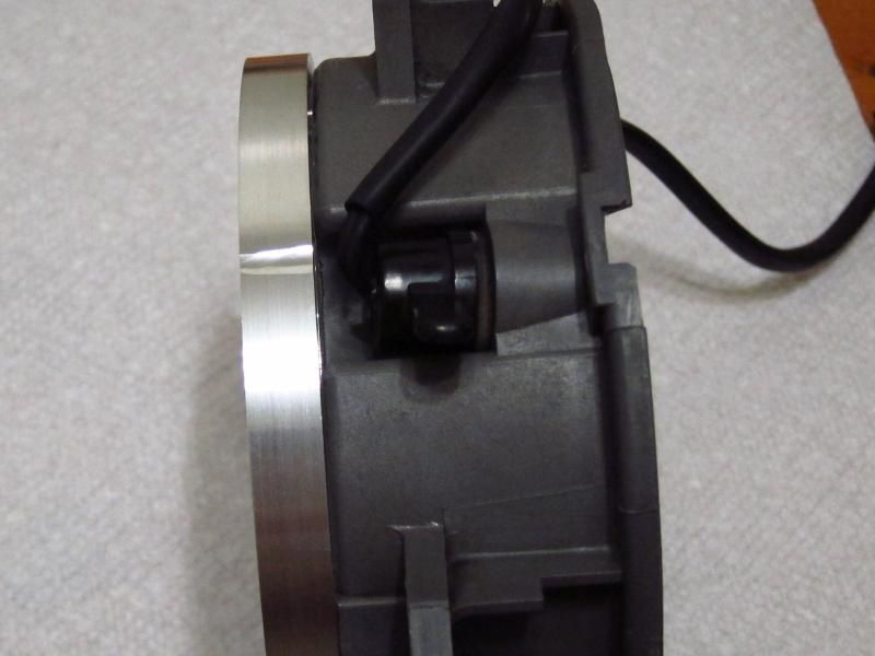
I will probably also mill a counterbore for the two mounting screws to get them flush (the heads would hit the FX-R projector assembly otherwise). I didn't account for the fact that a countersinking bit wouldn't fit here! I also plan to thin the outer ring by ~3mm (off of the outside) to get better clearance with the headlight bracket (it fits, but the rubber boot I plan to make would be really tight in there with this OD).
I also managed to get off by a couple of handle-turns down in the cut-out for the bi-xenon solenoid, and I forgot that the surface I was accidentally cutting through was a sealing surface.

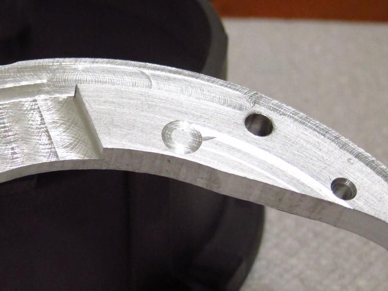
Up by the city light, I started out being off by half of a cutter diameter in the radius. It's a common rookie mistake (and I'm a rookie at machining).
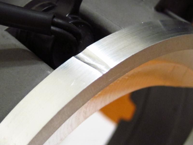
Lastly, there's a nibble in the outer perimeter from when I was cutting it out & the clamping wasn't quite adequate.
So, the next ones will be a lot cleaner. I'll probably do all cuts in 3 passes (-0.020", -0.005", 0.000"), spend more time with some of the centering setup, counterbore the 2 mounting holes, rough-cut the perimeter & finish it up on the lathe, and reduce the outer diameter by ~1/4". Yeah, it is probably overkill nit-picking this stuff. But, when you have the tools for it.....
