Author Topic: Stock Head Unit CM5908 Wiring Questions...  (Read 9053 times)

JP 91iS

  • Hero Member
  • *****
  • Thank You
  • -Receive: 0
  • Posts: 500
    • View Profile
Stock Head Unit CM5908 Wiring Questions...
« on: May 12, 2009, 11:57:14 AM »
I apologize for the long post, but I just wanted to clarify everything. Questions are in RED.

Picked this stock head unit up and am attempting to wire it up correctly.  It is the Alpine unit with the infrared fader:


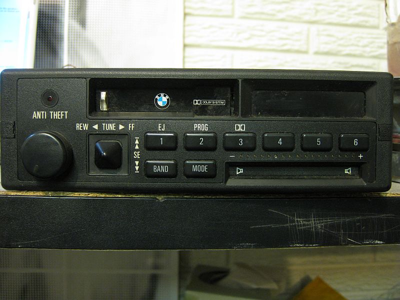
The stereo was cut with plugs from one e30 and the harness w/ amp and premium speakers was taken from a different e30 that had radio plugs cut already. I'm trying to connect the harness to the plug leads on the head unit. (yes I realize its really not worth the hassle, but it was mostly free so I'm just going to do it, ok?)


RR: Right Rear - BU/BL
LR: Left Rear - YL/BL
FR: Front Right -
BU - connects to-> BU/RD
                         BR - connects to->BU/BR (common ground splice)
FL: Front Left -
YL - connects to-> YL/RD
                      BR - connects to->YL/BR (common ground splice)

Should the Front Plugs have the Brown ground wires there or do they not go into the head unit? Do the Rear Plugs need some Brown grounds too?

MP: Memory Power -
YL - plugs to-> RD/GN - from power distribution
IL: Illumination - WT - plugs to-> RD/GY - from power distribution
PA: Power Antenna - WT
G: Ground - BR/BL - from ground distribution
+: Switched Power - VL/GY - from power distribution

??: Unknown - BL/BR - plugs to-> ??
??: Unknown - WT/BR - plugs to-> ??


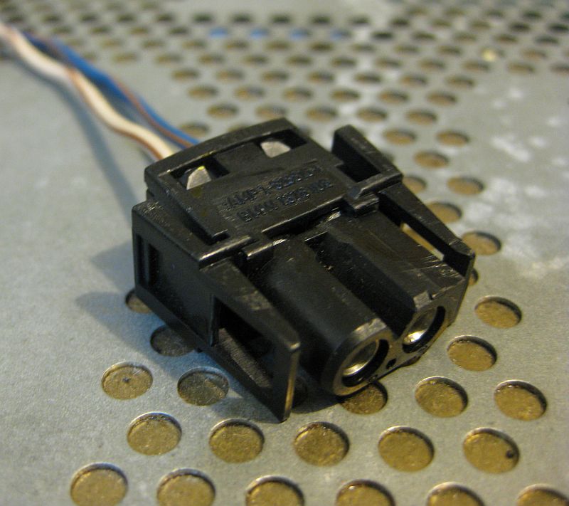
This plug is hardwired to back of the head unit: What does this plug connect to?

Thanks for any help, if anything needs clarification please let me know.
« Last Edit: May 12, 2009, 12:01:17 PM by JP 91iS »
-JP
Project M42: generating funds

JP 91iS

  • Hero Member
  • *****
  • Thank You
  • -Receive: 0
  • Posts: 500
    • View Profile
Info update
« Reply #1 on: May 13, 2009, 10:04:03 AM »
Thanks to help from John (ak96ss) who gave me the heads up on current wiring diagrams (link here), I figured out the extra ground wires.  I haven't hooked this up yet but I'm 99% confident that I've wired this up correctly.

Everything in my first post is correct, Except the 2 Brown wires that feed to the Front Left and Front Right radio plugs.  Instead they both hook together to a BR/BK wire that is factory spliced off the BR/BK wire to the radio ground.

Here is an image I drew up:


The part that was throwing me off is outlined in the red dotted square.  I think the harness I was using was intended to have the exterior mounted fader button, which is why the left and right channels had separate ground wires.

I still can't figure out what the extra radio plug is for (Blue/Brown wire and a White/Brown wire going to a 2-pin plug).  The diagrams I have been looking at show a "case ground" for the radio - but the wires in the diagrams are both brown and do not have a plug.
-JP
Project M42: generating funds

JP 91iS

  • Hero Member
  • *****
  • Thank You
  • -Receive: 0
  • Posts: 500
    • View Profile
Info update
« Reply #2 on: May 20, 2009, 05:52:53 PM »
Just wanted to add here that it works! I did a quick check of the functions and all speakers work and the bass/treble bal/fade works perfectly.  So the wiring diagram I drew in the previous post is accurate.  Radio works but I have not checked out the cassette since I don't own any! (yet)  I'll post back if anything is messed up.  Still don't know what the extra plug is for... I know its not the CD changer option - that is the round 13-pin port.
-JP
Project M42: generating funds