OK, as promised it is time for the photo dump of app the stuff I have done since the last set of photos.
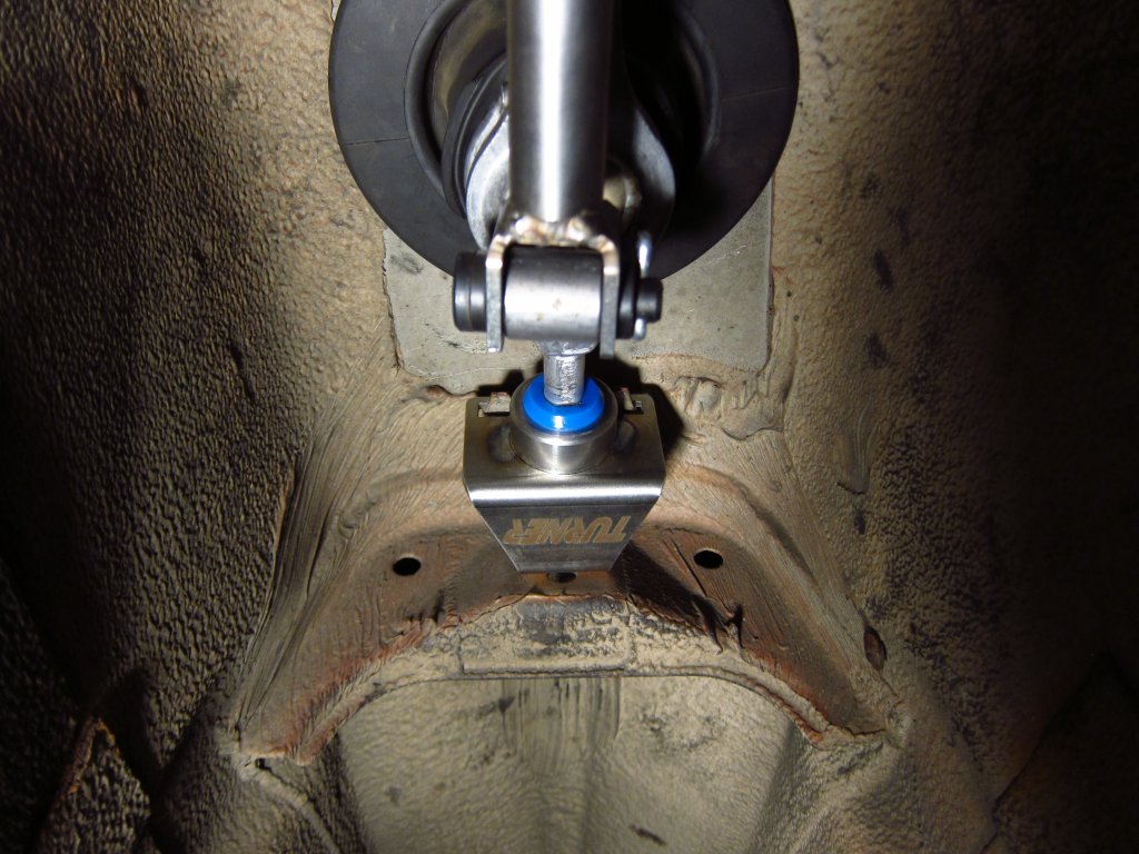
The rear shift carrier mount was in bad shape, and sort of expensive to replace, so I opted for the beefier Turner Motorsport upgrade. It was only marginally more expensive, and it would eliminate the last of the stuff in the linkage that was making extra slop. It does not fit exactly like the original one (the angle is a little different), but it is good enough to work properly. It was listed as being E30 compatible, so who knows.
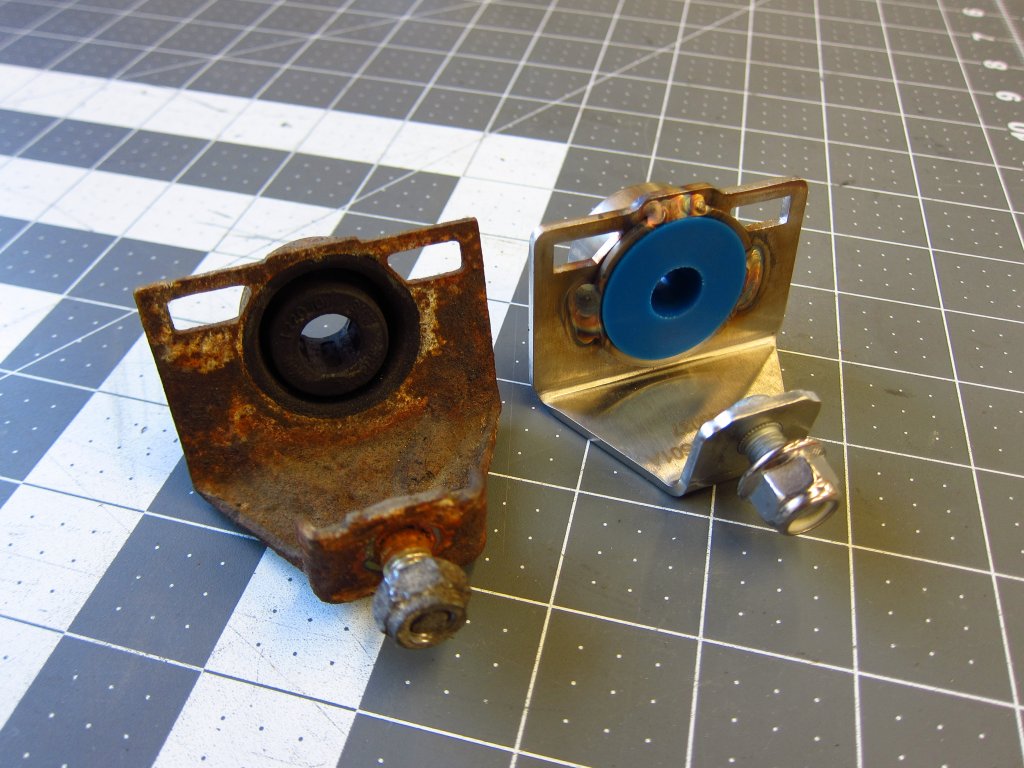
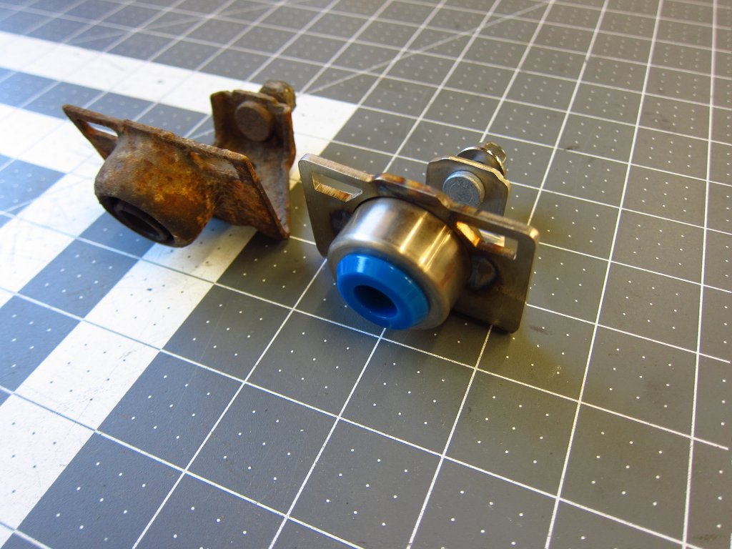
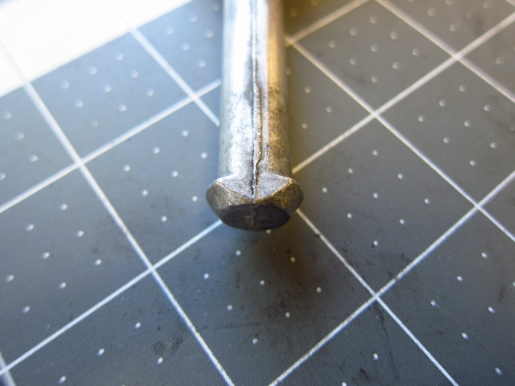
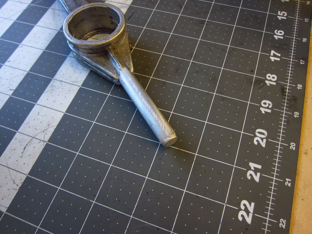
I did make one small modification to the carrier. Rather than jam the mushroomed end through the new poly bushing (teehee), I just channeled my inner rabbi and filed it down. In normal operation the mushroom serves no function and just makes removal of the carrier more of a pain.
Here it is installed on the car.
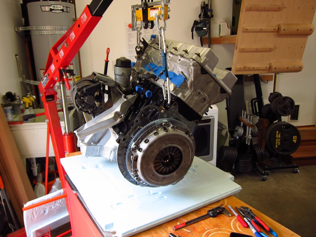
Here is the nice new 7.4lb RHD flywheel installed on the engine.
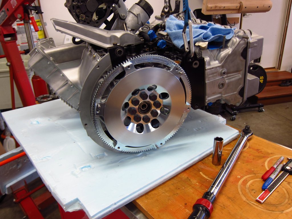
I also bought the proper crank locking tool, which is a hell of a lot easier to use than the big ½ cold rolled plate I drilled holes in 15 years ago. It was $85 at Pelican Parts. The weight of the engine was more than enough to keep things from moving around as I torqued the FW bolts to 120 ft-lbs.
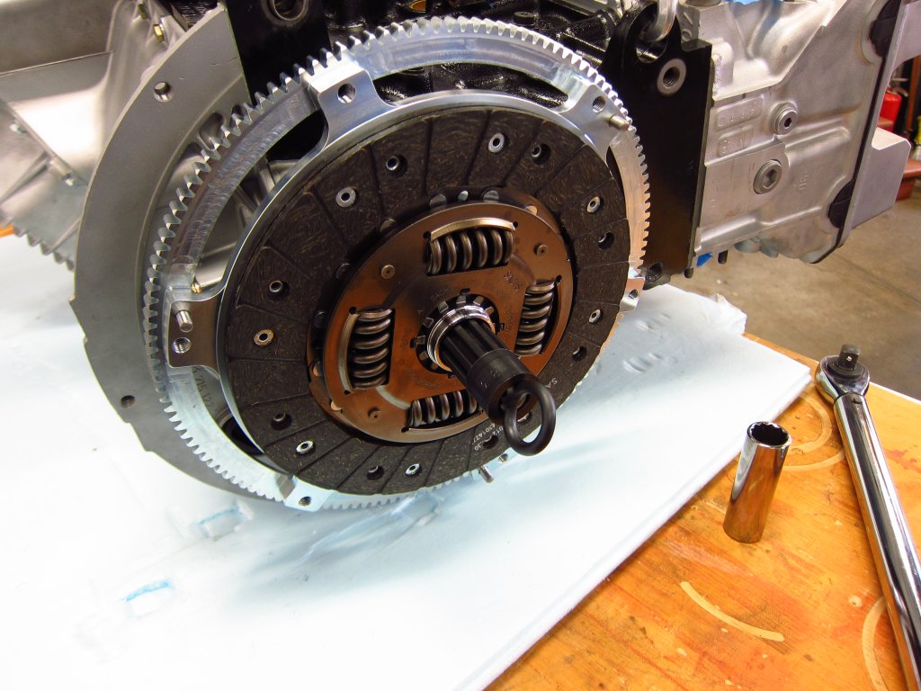
Next up were the clutch disc and pressure plate. The FW and PP were dynamically balanced together and came ended up with <0.9 grams of total imbalance in the end. Cardelli Motorsports in San Mateo, CA did the balancing for me for $100 cash.
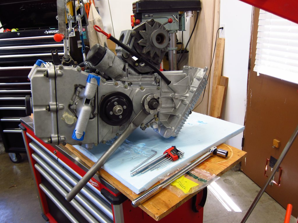
Next the transmission was bolted on. That was a super easy task with the engine up on the mobile workbench, and I got it to slide right into place. One hand to support it (so as to not load the pilot bearing excessively), one to start one of the big top bolts. And no, I did not bother cleaning the transmission. I had thought about it, but at that point I needed to get the project moving and out of the garage.
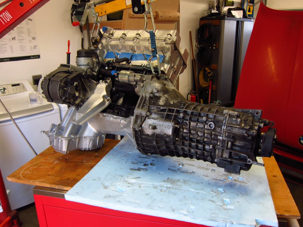
And there it was, mostly ready to go back into the car. It had a nice new ground strap as well. I replaced all of the ground straps (engine, alternator, hood) with new ones from Bavarian Restoration.
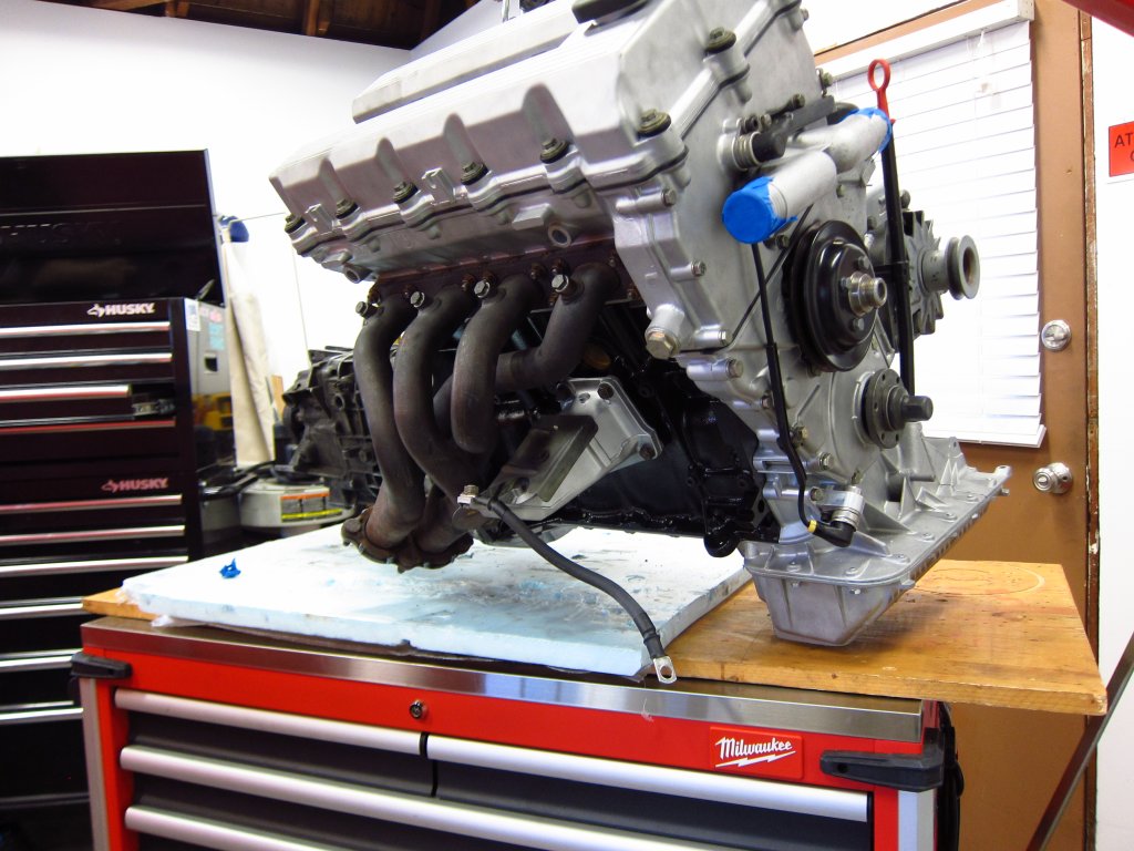
There were a few odds and ends to take care of before dropping the engine back in. Among them was purging the fuel lines that had sat for 7 months. This was pretty easy to do by looping the old feed hose onto the return hardline and hooking the battery up to the pump. If you hook the battery negative to the chassis and the positive terminal to C101 pin 13 (fuse box side) it will run the pump and have fuse 11 there for protection. I ran it for a few minutes and that was that. All flexible fuel lines up front were replaced with new ones.
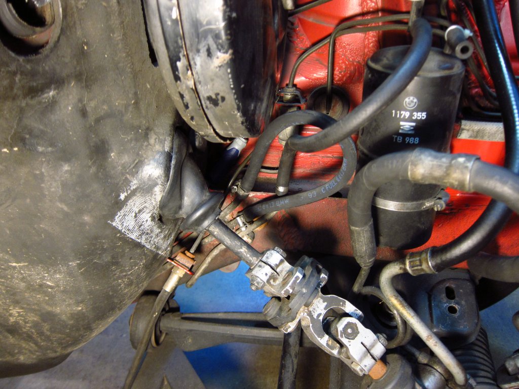

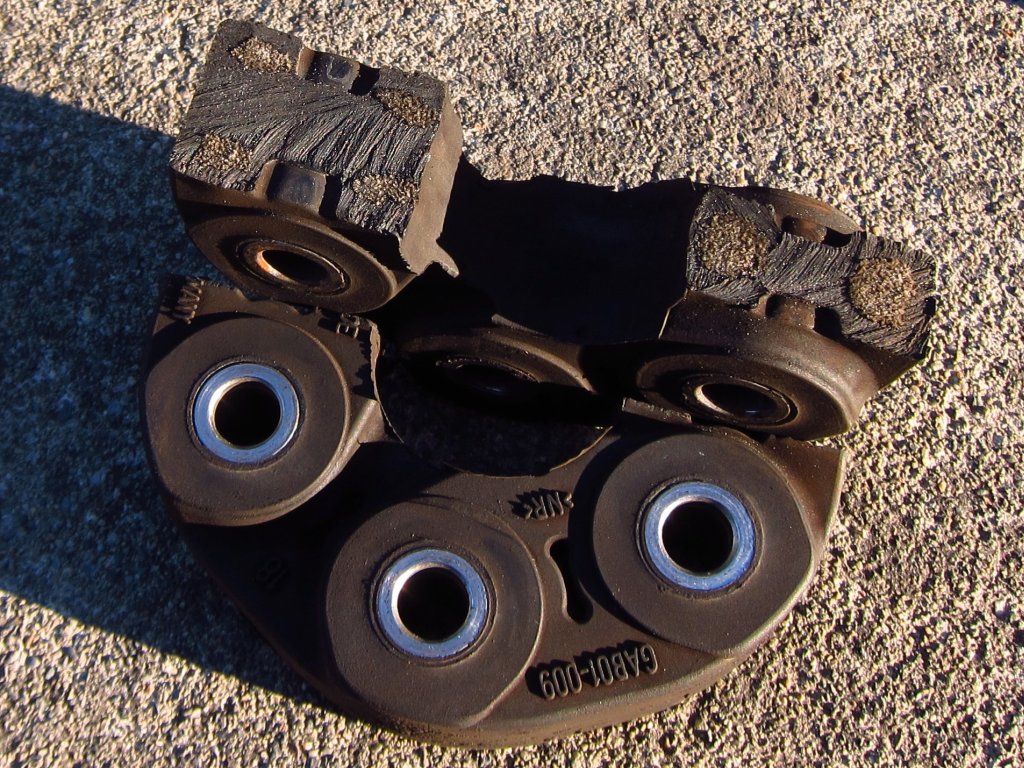
Oh, and at some point I decided to cut my old flex disc in half to see how it is constructed. They are directional and need to be installed properly to put the proper parts into compression when applying engine power, leaving the other less stiff parts free for taking up vibration when engine braking. These things have some beefy fiber bundles inside (maybe aramid or glass, I did not check too closely).
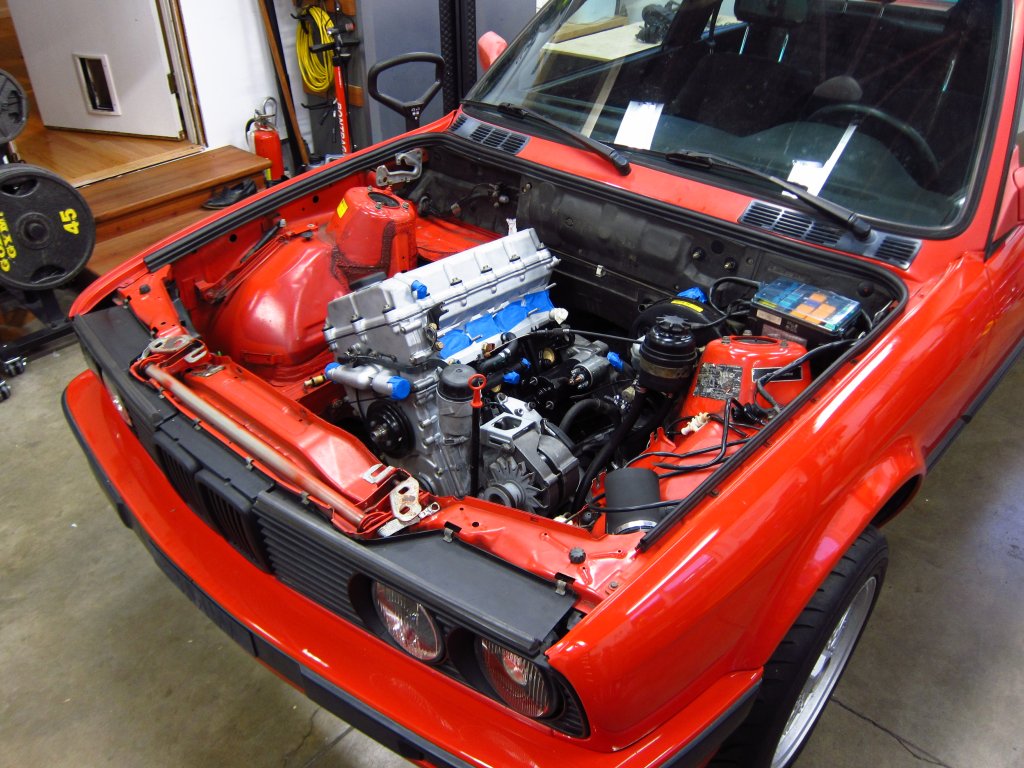
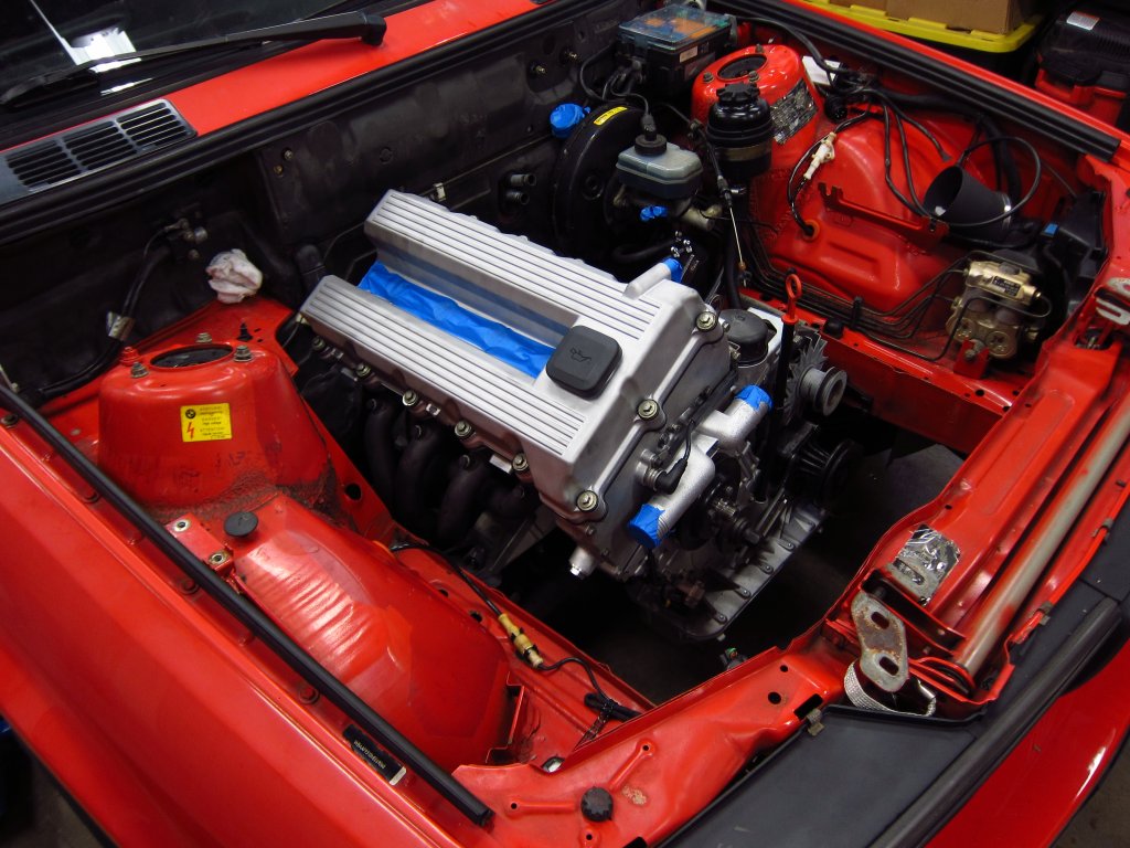
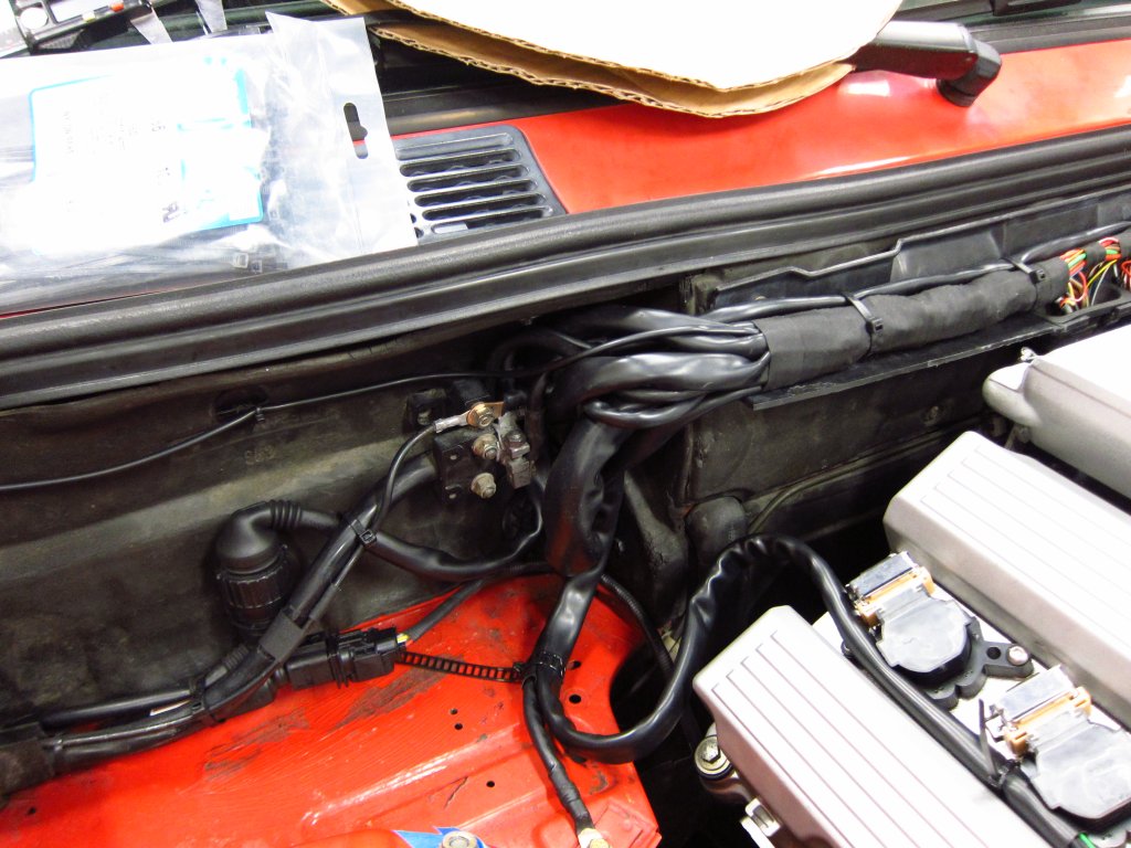
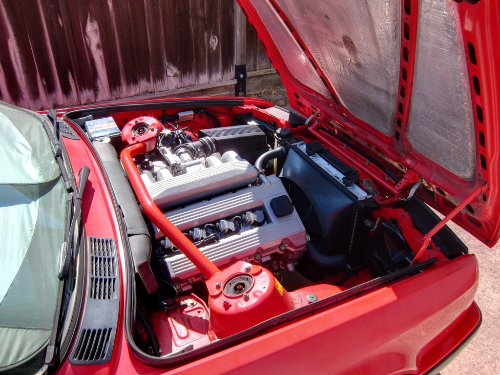
Anyway, here it is plopped into the car. The main items to reinstall first are the engine mount arms and mounts and the exhaust header. That saves you from a bunch of reaching around under there, and getting the header in/out with the engine in place is a hassle. A few of the other accessories were also installed. Leaving the intake manifolds off, and having the entire firewall wiring tray out, made it super easy to get in. I almost did not even bump the engine or transmission into the car at all while tilting and lowering it in. In the past the main trouble spot has been up at the firewall where the intake manifold would hang up on the wiring tray (or the main wire loom).
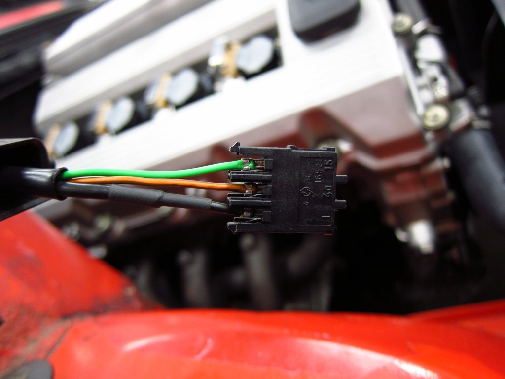
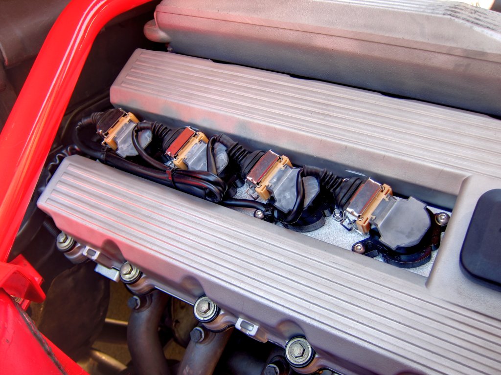
After bolting on some more stuff, I turned my attention to the engine wire harness that I had completely rebuilt. The final remaining task was to trim the ignition coil leads to their final length. I took measurements of the wires, where things were stripped, etc., on the original connectors and duplicated that with the trimmed ones. All of the sheathing is new since I changed up how the bundles route from the main loom on the firewall, and getting it all neatly in place was a bit of a chore. The main 0.56 ID sheath that the 12 wires for the 4 coils ran through split into four 0.25 sheaths, and to get clearance on the ends for the heat shrink tubing and stuff I needed to slide it all up into the main one. Windex for the win, it does wonders for enabling things to slide around while also drying quickly. Anyway, I am getting way too excited about wiring lol.
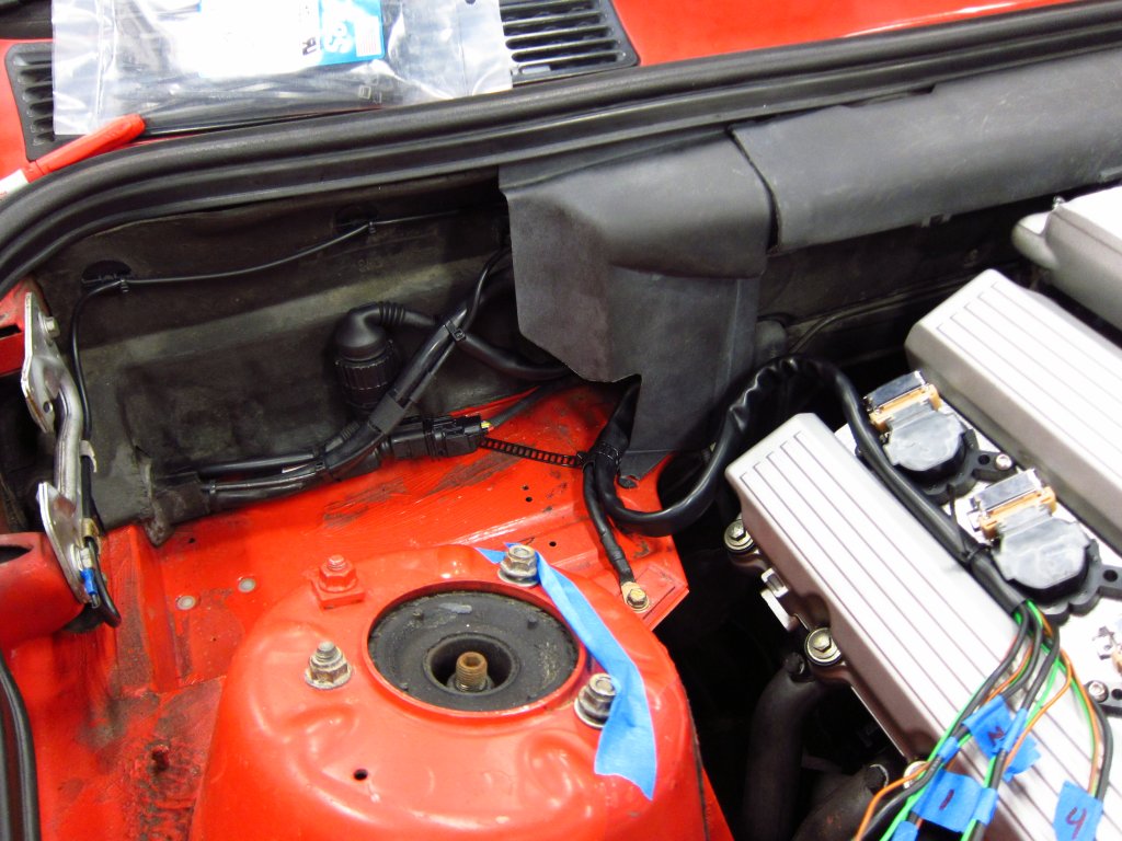
I started by figuring out how exactly I wanted to route the main bundle to give it a proper service loop for strain relief, and then I played with a few different configurations for the individual leads. The one I settled on worked out so that none of the smaller looms would rub on the metal plug retainers, none of the plug ends would be subject to any movement from the chassis loom and everything could be conveniently zip tied into place and serviced in the future. This is a COP plate kit from HQ Autosport, but I made some changes to the fasteners and added some washers as spacers for ergonomic reasons (maybe I will do a write-up of how I improved upon it sometime).
OK, I will try not to type another giant paragraph about wiring. As much of a pain as it is, it is sort of fun if you are doing it right.
Once things were roughed into place, I cut the leads and sheath pieces I would need. From there it was just a matter of crimping the terminals on and putting the connectors together. As another FYI point, the rubber boots for these connectors are a real pain in the ass to get onto the 0.25 sheathing. It is the same diameter as the original sheaths, but the boots are either not intended for use on that size, or they are supposed to be REALLY snug. Getting them onto the sheath was a bitch
be warned!
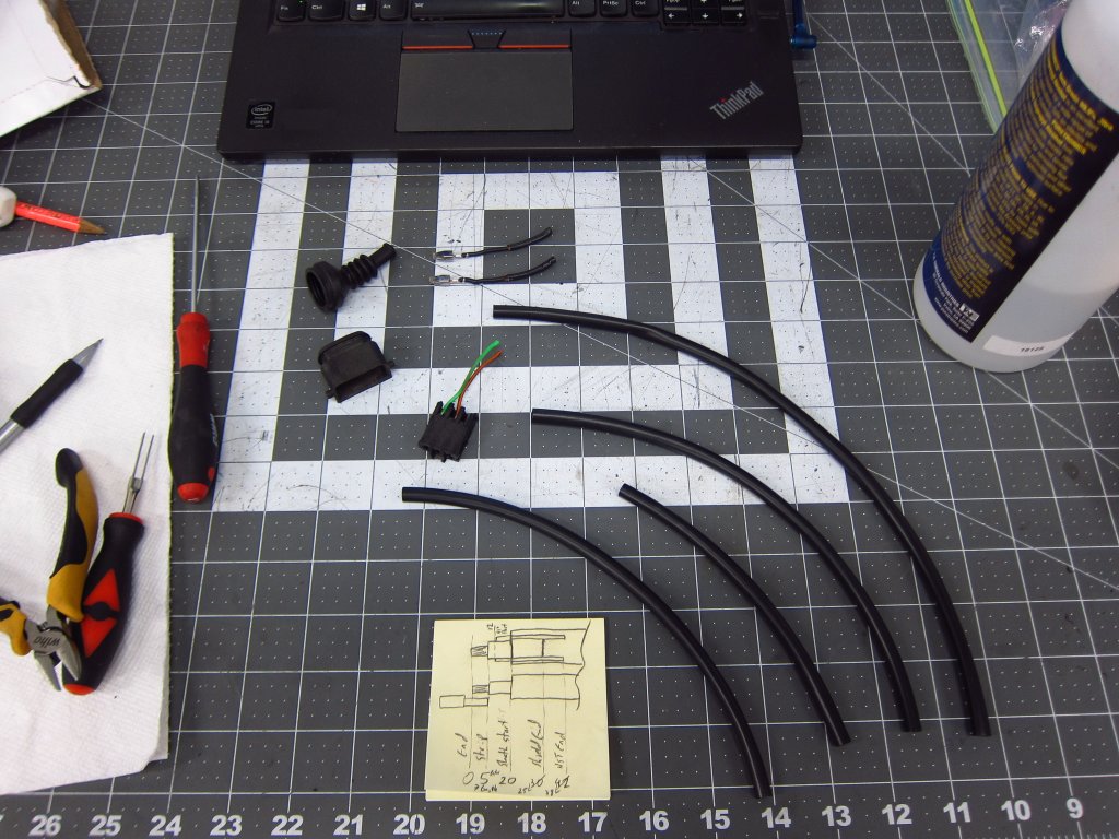
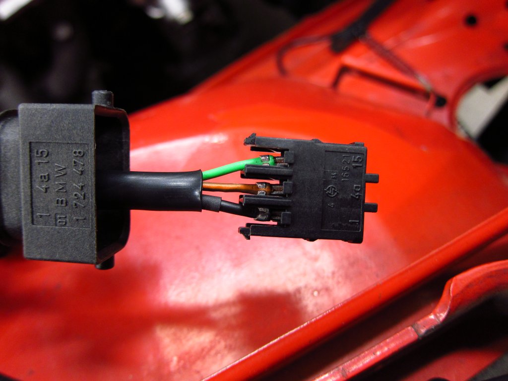
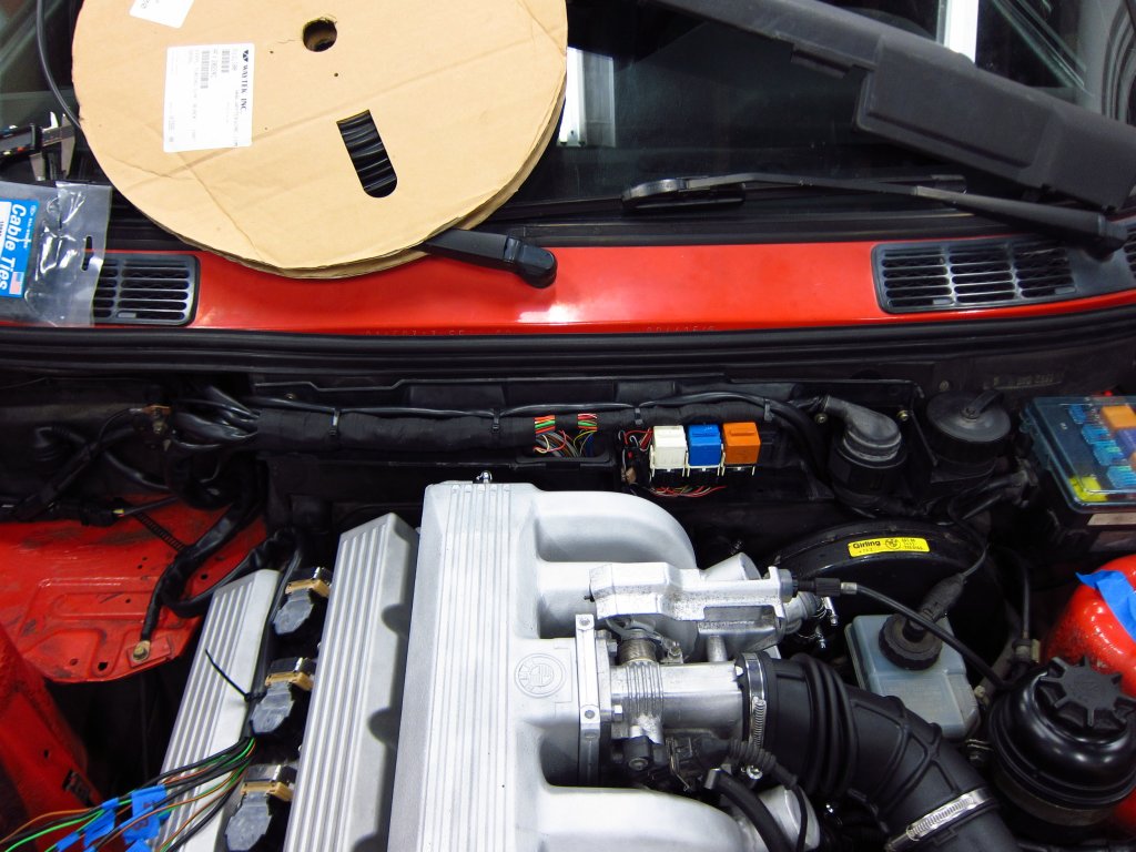
Here it all is laying in place before I actually finished it up.
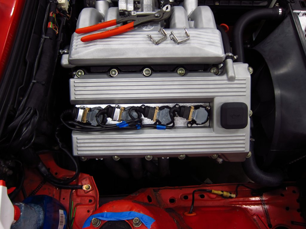
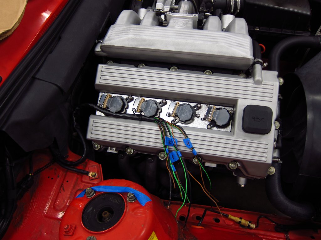
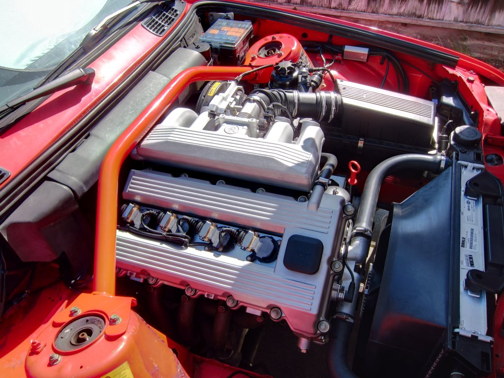
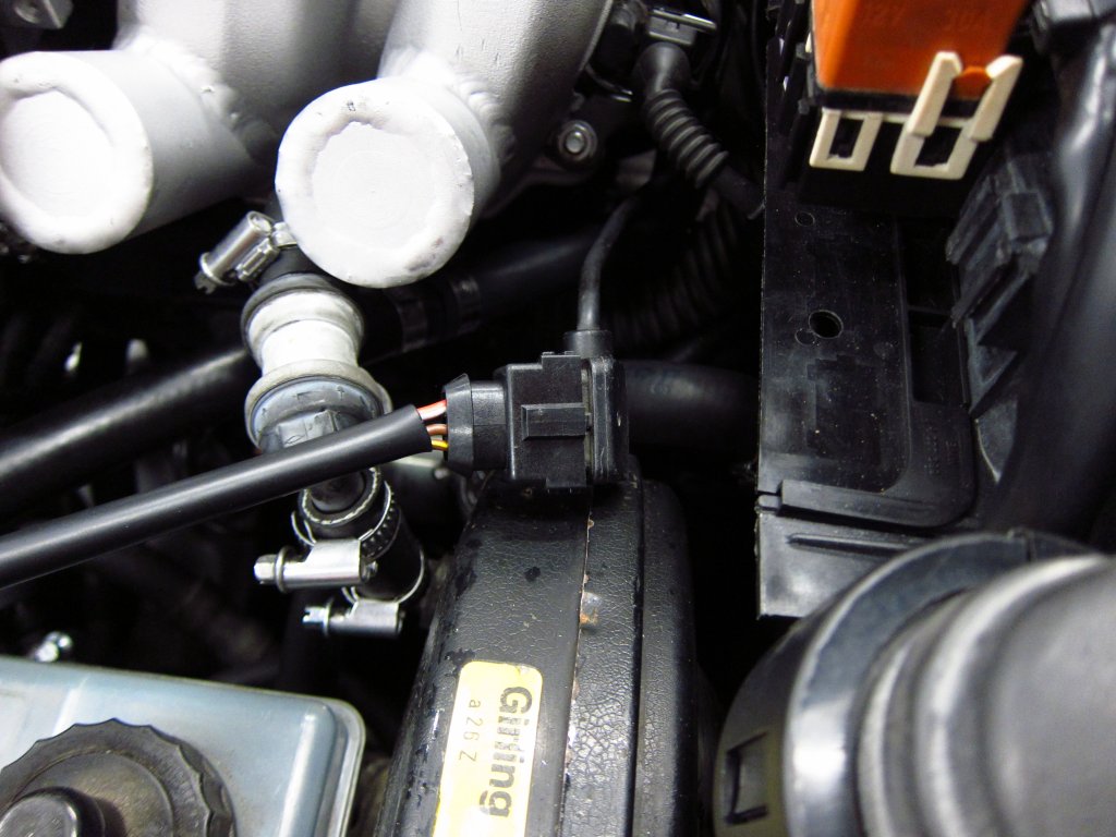
And here is the final setup. I am pretty pleased with the little service loop that connects the chassis to the engine. Compared to how I trimmed and routed stuff on the old harness back in 2006 when I invented the COP conversion (fun fact!), this is immensely better. Considering that shitty wiring job lasted 14 years with no broken wires or pierced insulation, this should outlive me.
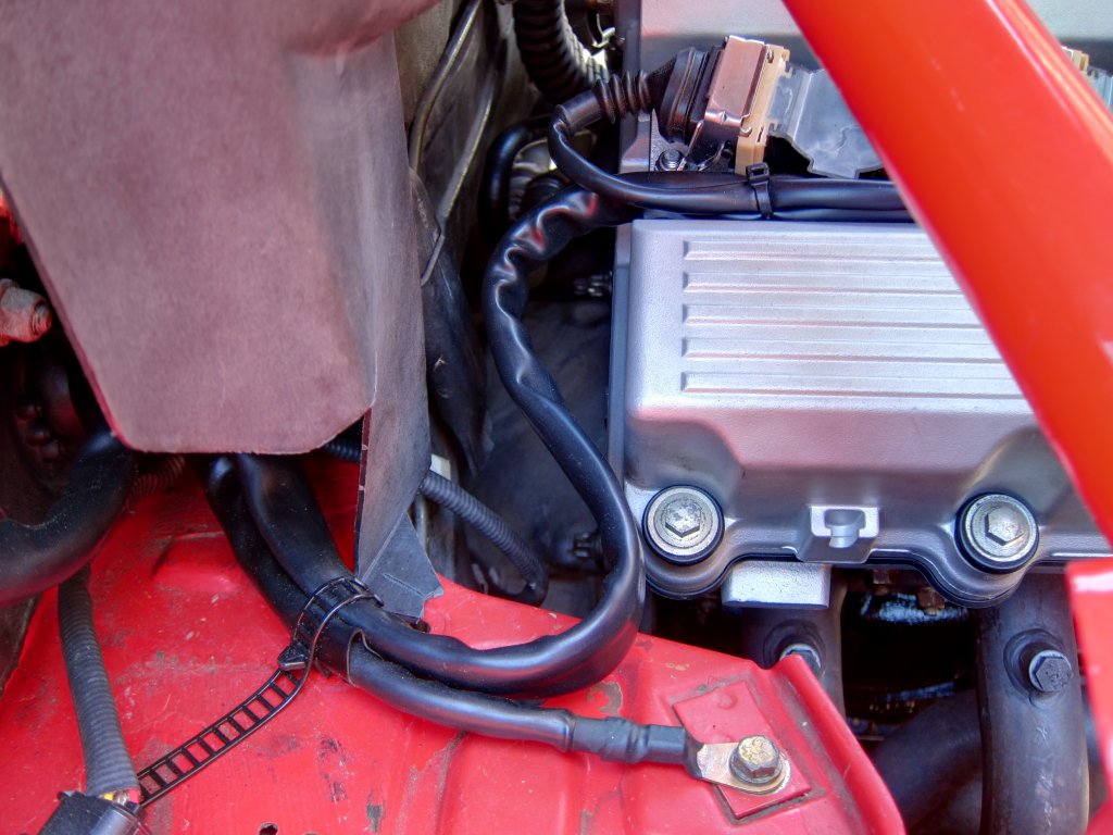
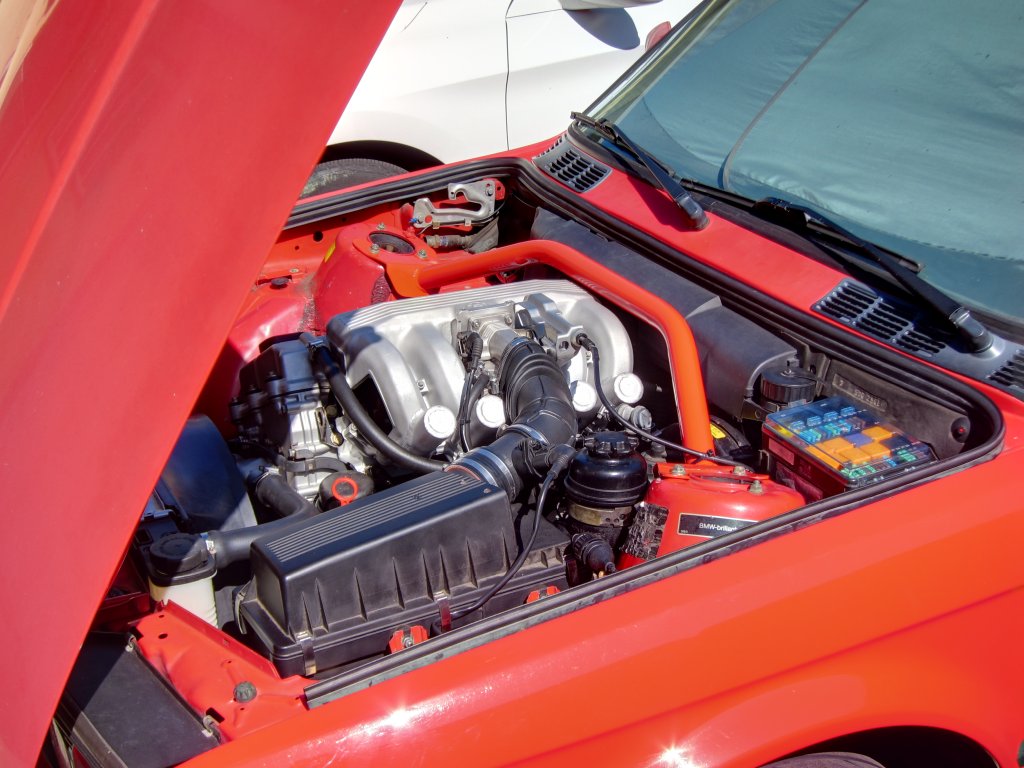
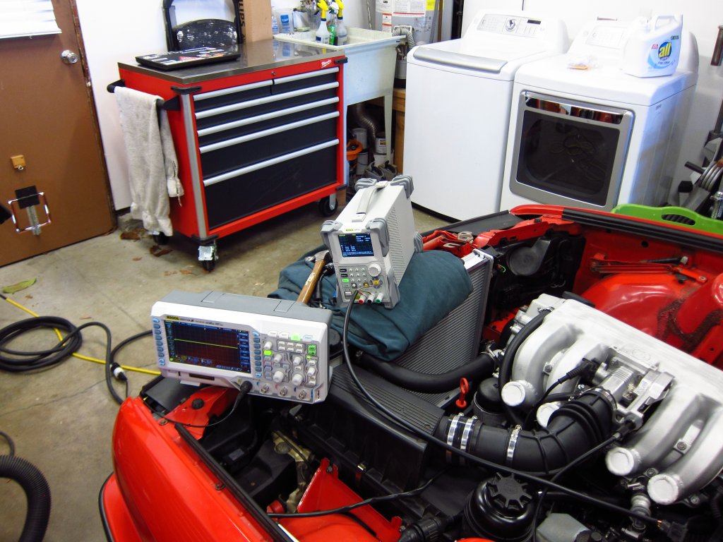
And so, here it all is today. I have ~160 miles on the engine and have been driving the dog shit out of it. Damn it is fun, and despite being able to feel the cars age, it is a hell of a lot more fun than most newer cars. All drivetrain and suspension stuff is effectively new, but its still based on 40 year old automotive design, so the way it handles and reacts feels a little dated. BUT, it is a go-kart compared to heavy newer sports cars, and despite being slower it has a feel that you dont get anymore. I had mostly forgotten how much I enjoy driving this thing over the last 7 months of waiting and toiling!
Other random crap
.
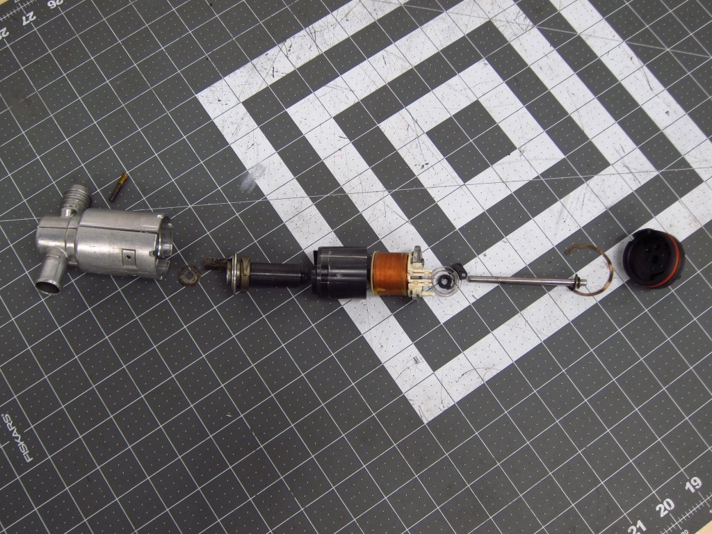
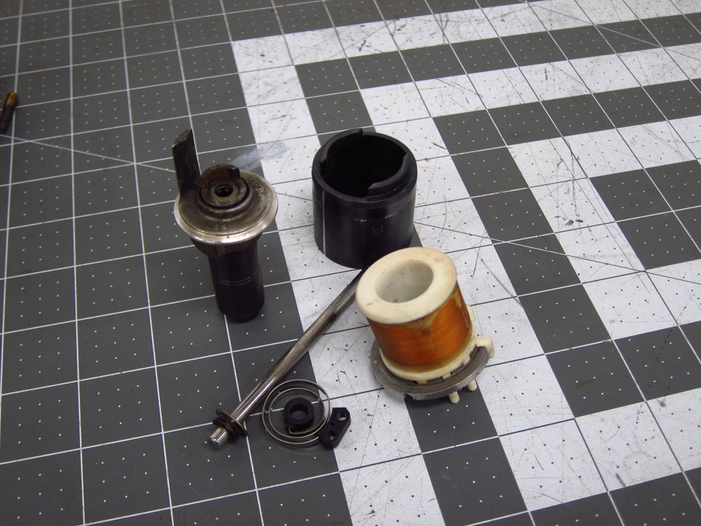
As you all have seen, I was chasing down gremlins as I tried to get it to run. Since roguetoaster sold me an ICV that was in cleaner shape than my old one, I decided to dissect the one I took out. Ive never seen one opened up, probably because you have to totally destroy it to get it apart. The outer housing is staked in like 10 places (both the end, and on the sides) and one part is pressed in. Ultimately it is just a simple little electric motor. The design is sort of unique, and clearly not intended for high torque, but it works well enough. The single coil that makes up the stator interacts with the magnetized center cylinder and funky-shaped upper section that serves as a rotor of sorts. The I assume that the shape of the ferrous top is what allows it to interact with the symmetric magnetic field from the coil (I wouldnt expect it to generate motion at first glance, were it not for the wedge shapes at the top which you can sort of see in the next pic).
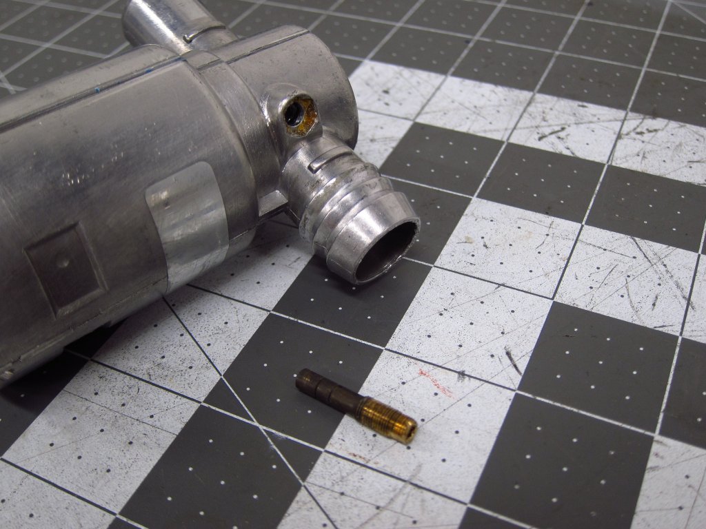
This set screw (which is epoxied into place) sets the end stop for when the thing is not energized. It leaves the ICV open an amount that corresponds to the engines air needs at the designed idle speed, hence why unplugging it usually leaves the car idling reasonably well.
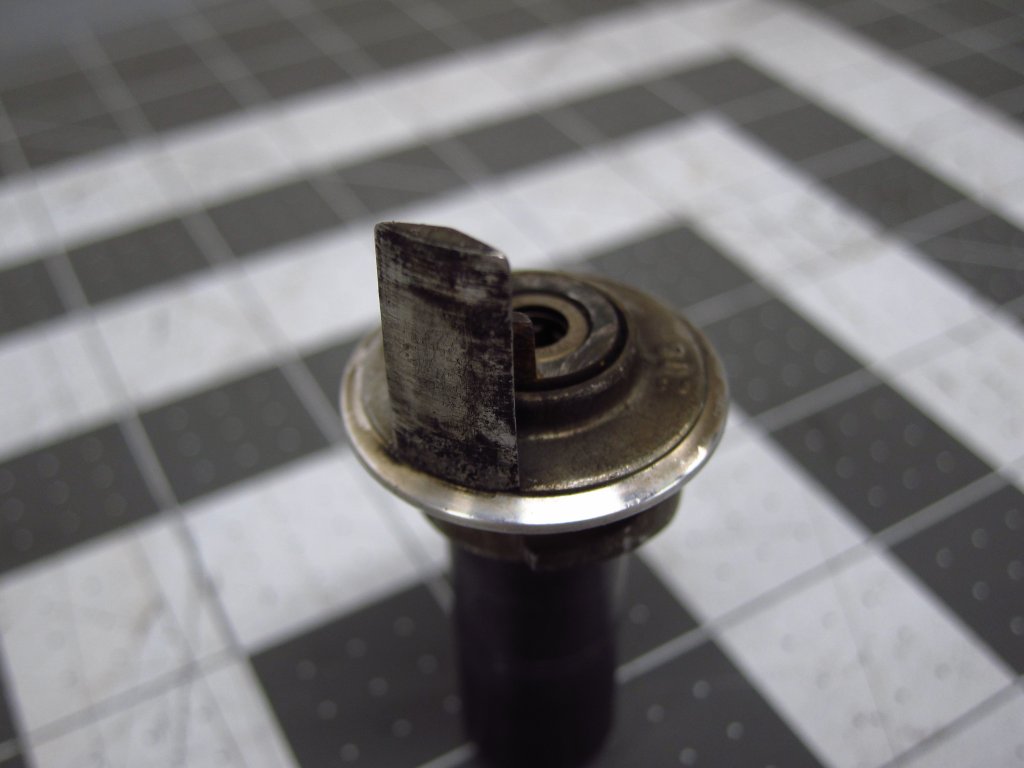
This little flag is the thing you see moving through the hose barb. The ECU sends a 100Hz PWM signal to the ICV, and this little door flaps open and closed at that rate. Varying the on/off time in that 100Hz signal is how the average opening amount is created by the ECU to control idle (Motronic also uses enrichment and ignition timing to control idle speed and stability).
Back when my fuel injectors were stuck shut, I tried to free them with a programmable power supply (you can program voltages and on/off times to make a pulsed output). I also had some spare wire harnesses that were cannibalized to rebuild the one in the car, so I took more parts from them and made my own little debug connectors for the injectors (and some other stuff just in case).
Phew
there it all is. Things are mostly wrapped up now, and I will make new threads for the other non-rebuild stuff I came across in this project. Im going to cross section one of my old ignition coils for fun, and probably take apart the old MAF sensor element. Mostly I need to remember to make a DIY for how to improve the HQ Autosport COP bracket kit, and try to get measurements of the wiring dimensions. Granted, many of the measurements are useless unless you totally rebuild your harness since the stock ignition coil wire routing wont leave you enough length to do it my way.
Thanks a lot to everyone for all of the input, encouragement and discussion over the many months since this all started! The E30 community is probably the #1 reason why I still have this stupid car lol.
