Suspension and Driveline Overhaul 2016 (Photo Log)

Author Topic: Suspension and Driveline Overhaul 2016 (Photo Log)  (Read 12556 times)

bmwman91

  • Administrator
  • Legendary
  • *****
  • Thank You
  • -Receive: 33
  • Posts: 2798
    • View Profile
    • http://www.e30tuner.com/
Suspension and Driveline Overhaul 2016 (Photo Log)
« on: February 29, 2016, 04:21:29 PM »
I am going to document my partial-refresh of my suspension and driveline in this thread. It is an OEM+ type refresh since the car is mainly used on the street and in some autoX. From my experience, OEM suspension bits are really the best way to go on the street since they have enough compliance to absorb lousy road conditions, which helps a lot with traction. I ran all poly stuff and a 2.5" drop from 2002-2007, and while the "bcuzracecar" feeling was fun, it got old and made the car impractical for my needs. A big part of why I went with the poly bushings was the fact that I was a broke college kid and didn't want to pay a shop to press in new OEM parts lol. Anyway, in 2007 when I put in all new, all-stock parts, the car actually handled better on the street. Since it has been nearly a decade and around 70k miles, things are starting to wear out again and I am going to replace them, along with a bunch of other wear-items that probably need it.

All parts are either genuine BMW or made by an OEM supplier.

Stuff that is getting replaced:
- Front wheel bearings / hubs
- All front wheel bearing dust covers and the axle nuts
- Front control arm bushings (centered E36 M3 rubber bushings)
- All 16 lug nuts
- Rear wheel bearings
- All rear wheel bearing covers, circlips, nuts, etc
- Rear subframe bushings
- Rear trailing arm bushings
- Diff bushing (solid rubber 325iX version)
- Turner Motorsport rebuilt driveshaft (remanufactured by Beyer Driveline)
- New guibo and CSB
- EDIT: 325iX VLSD unit that was mistakenly sold to me as a Quaife (lol)...working on other options now
- Fuchs Titan Sintopoid 75W-90 gear oil and a new cover gasket
- Both axle half-shafts
- E-brake shoes and related spring bits
- E-brake cables
- Both sway bars (removing the beefy ST bars in favor of OEM/Mtech bars)
- All sway bar end links, shells and bushings

I installed Bilstein HD shocks about 25k miles ago, so those are most likely just fine still, hence why I am not replacing them.

Other than that, I am running stock springs and the car has ST sway bars in it still (22mm front / 19mm rear), but I am looking to go back to stock sways. This is because stiff sways don't really provide much benefit on the street (IMO) and I get nervous taking the car off-road with them since I already had one chassis mounting point rip out a while back. Once I find a set of OEM M-Tech sways (20mm front / 14.5mm rear) I will install those and all new links + bushings all around.

So, anyway, that's the background. Now it is time for some pictures and hopefully some useful how-to info for others. Today I replaced the front wheel bearings and front control arm bushings. These were super easy items and didn't require anything particularly special.

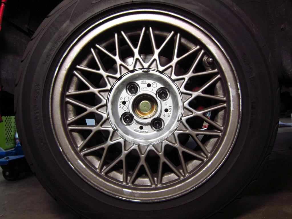
So, start off with the front wheels. Nothing too special here, just lots of brake dust!


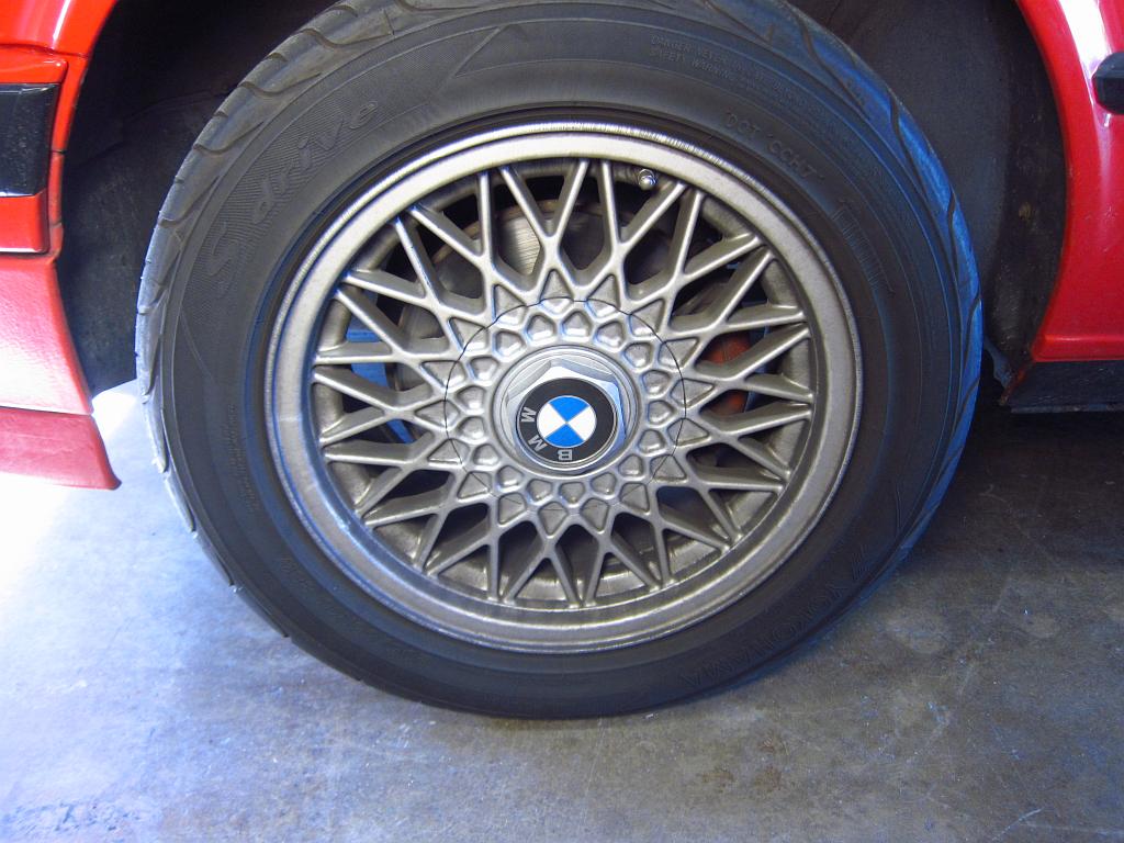
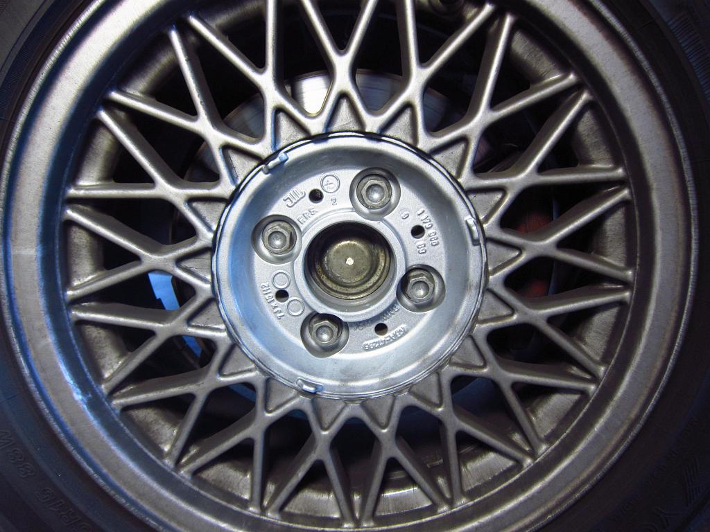
Pop the wheel cap off and you'll see the dust cover in the middle. I was thinking that I could pry it out with the wheels on the car, but I would have banged up the paint so I took the wheels off. The dust cap is in there tight, and you will almost assuredly wreck it during removal.


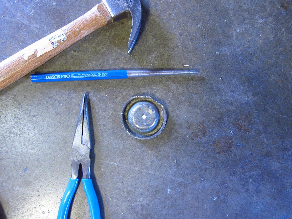
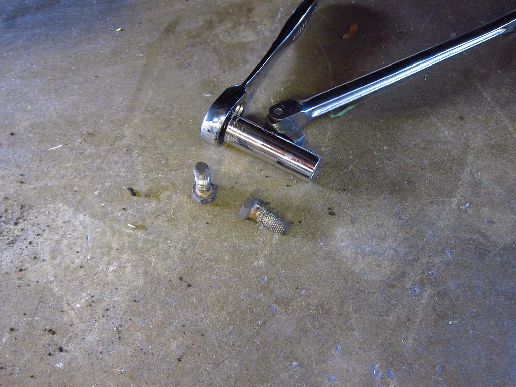
So, to get the dust cover off you just need a few basic tools. I like to use a small hammer for stuff like this to reduce the risk of damaging other stuff, and it is a lot easier to aim the swings. Just take your punch and use it to pop the cap's lip off in a few places. From there, you should be able to pull it off with some needle nosed pliers.


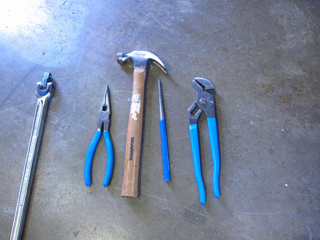
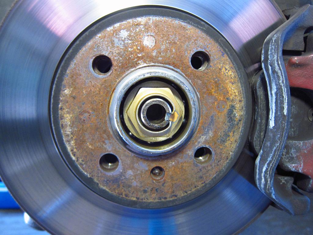
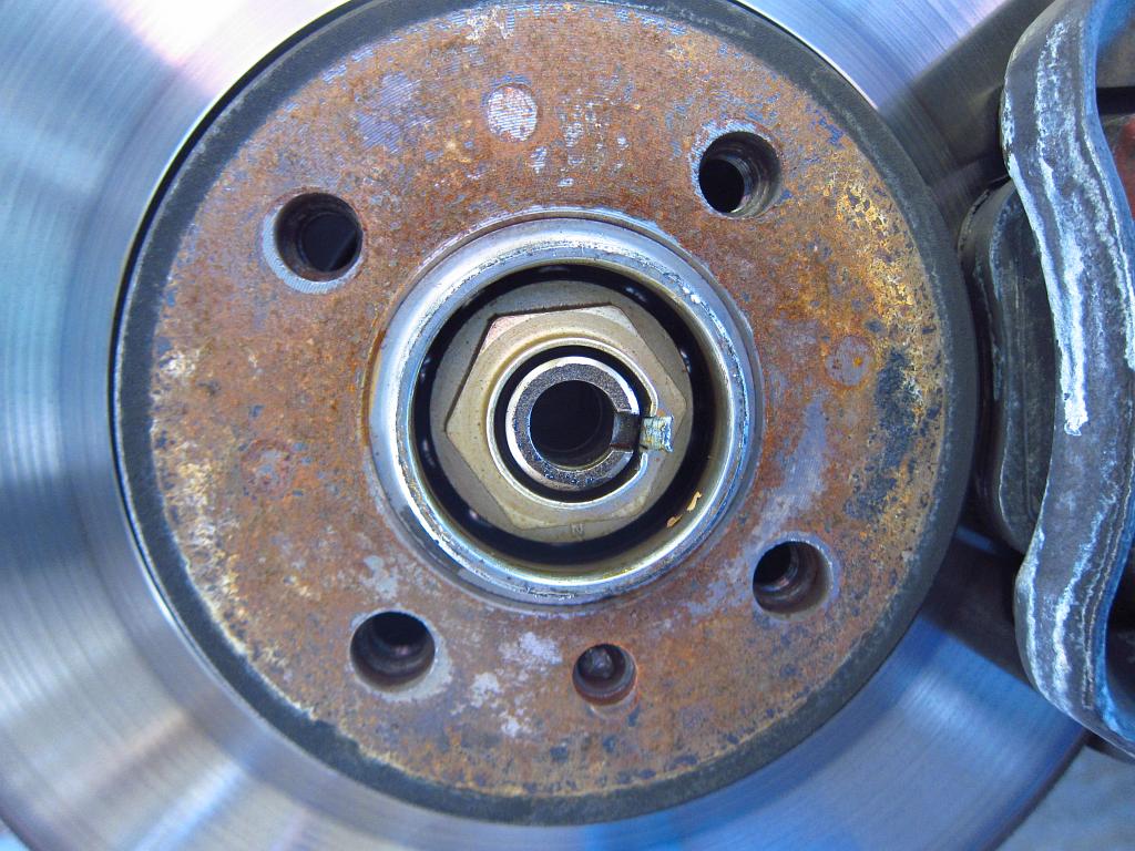
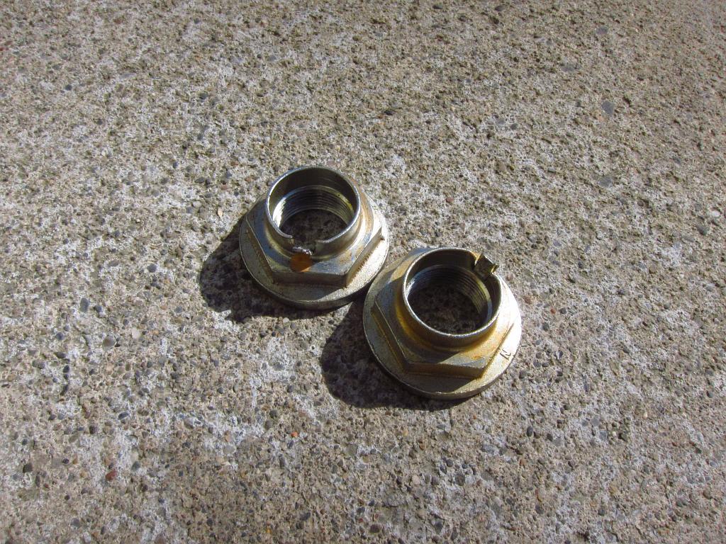
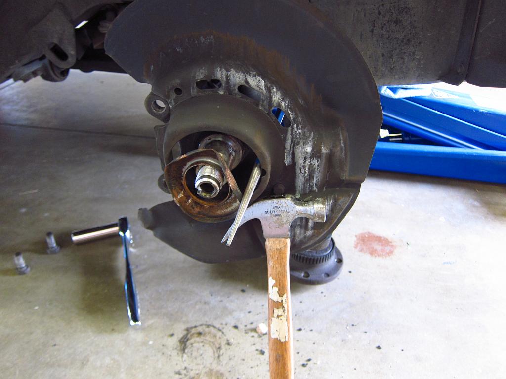
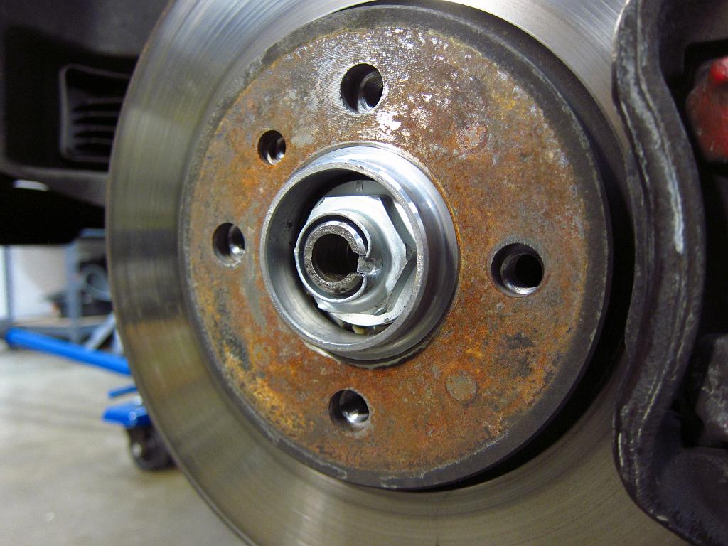
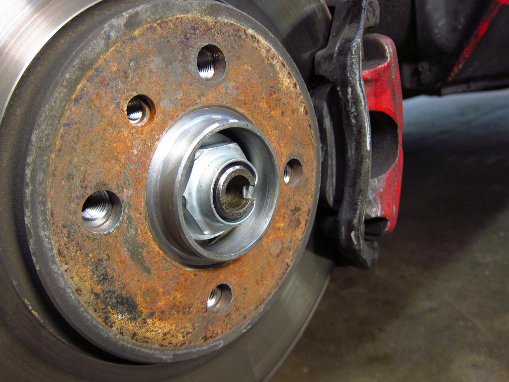
With the cap off, you can access the axle nut. You will need to bend the lock tab out to remove it. A few careful smacks with the hammer and punch will have it out of the way in no time. Be careful not to catch the punch on the axle shaft though; part of it is right below the tab so don't put the punch in too deep. Also, I used the mallet and a flat blade screwdriver to push the rest of the nut’s bent edges away from the axle just to make sure that nothing would catch.


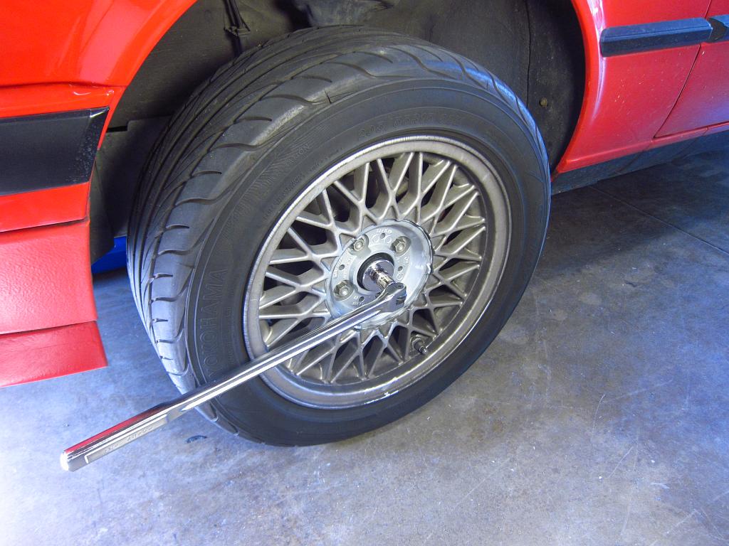
Now comes the fun part. This 36mm nut is spec'ed to 210 ft-lbs of torque, so you will need a breaker bar and 36mm socket to remove it. You must put the wheel back on for this because you don't want to load up the control arm's ball joints (or the shock) with your body weight. The wheel is just there to provide support to take the load off of the suspension. Get your breaker bar on there and step on it. Maybe give it a little bounce, just enough to get it to break loose. Do NOT turn the nut more than 30 degrees or so while the wheel is still on the ground. Once the nut is broken loose, jack the car back up and remove the wheel. Then you can remove the axle nut. This is because the bearing will probably come apart if the car's weight is on it when the nut is removed (the nut holds the inner and outer races together).


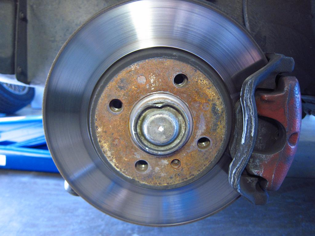
You will need to remove the brakes to get the hub off. This is pretty easy. Just take out the two 19mm bolts that hold the caliper carrier in and you can move the entire caliper + rotor assembly out of the way. Secure it to something so that the hydraulic line is not under tension (I zip tied things to the springs). Try not to get grease or anything on the rotor while you are handling it.


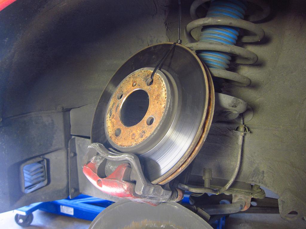
Next, you will be removing the bearing+hub assembly. Your results will vary here, but if the dust covers were intact there is a good chance that this will be VERY easy. In my case, I was able to get both bearings off of the axle by pulling with just my hands. Just make sure that you pull straight and don't cock things. Other people have reported that they needed a little help from gear pullers or that they were able to put the wheel back on and pull on that. A few unlucky souls have probably had to take it to a shop because things rusted somehow.


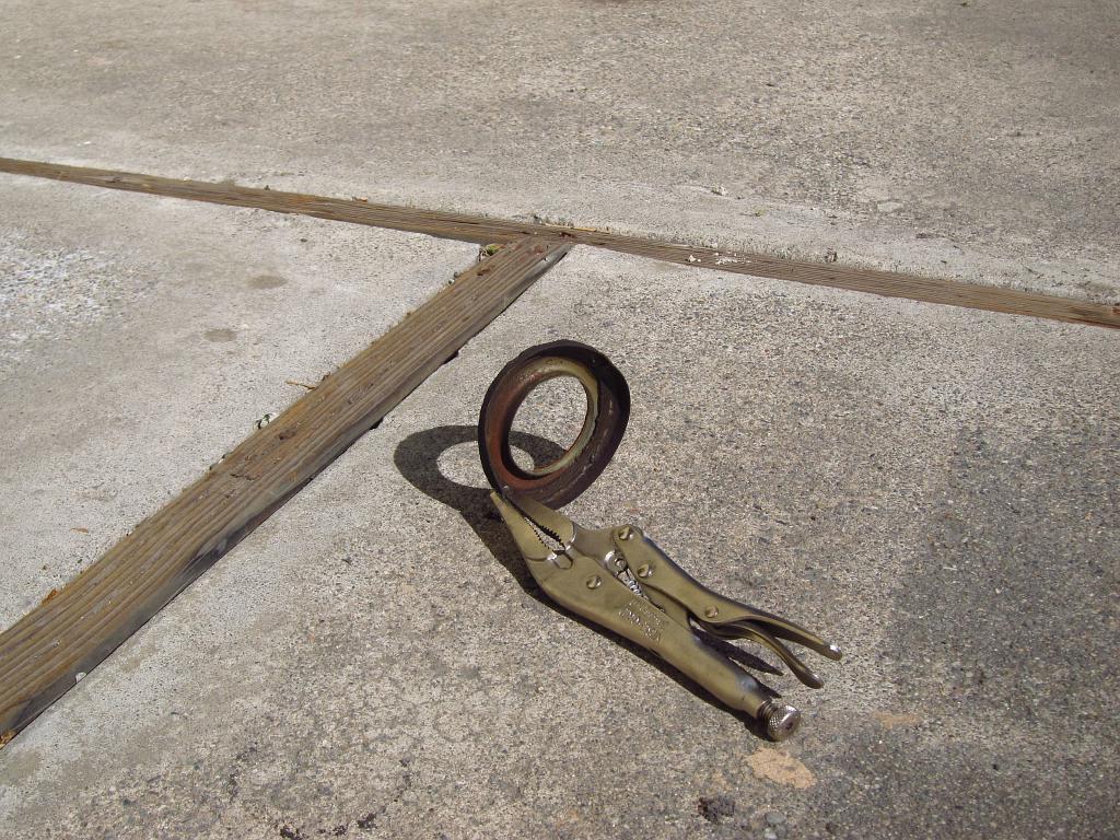
Removal of the inner dust covers is a little bit of a pain. These do not necessarily need to be replaced, and if you clean them off they are probably perfectly fine to re-use. I wanted to replace them anyway since they are inexpensive and I am sort of OCD about stuff like this. So, to get them out you should give them a few good whacks with a hammer and punch from behind, and then you should be able to pull them out with some needle nosed vise grips. Just be mindful of the axle shaft and don’t scrape it up.


With the old cover out, clean things up and scrub off any rust or brake dust that has built up in the back.


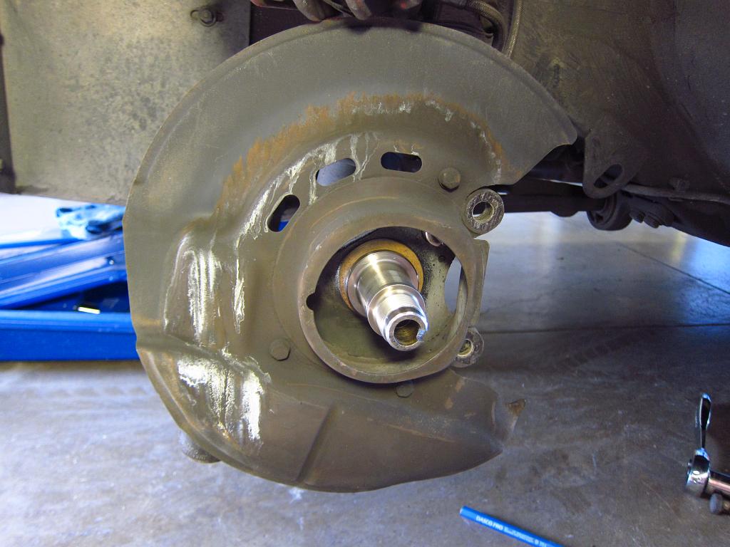
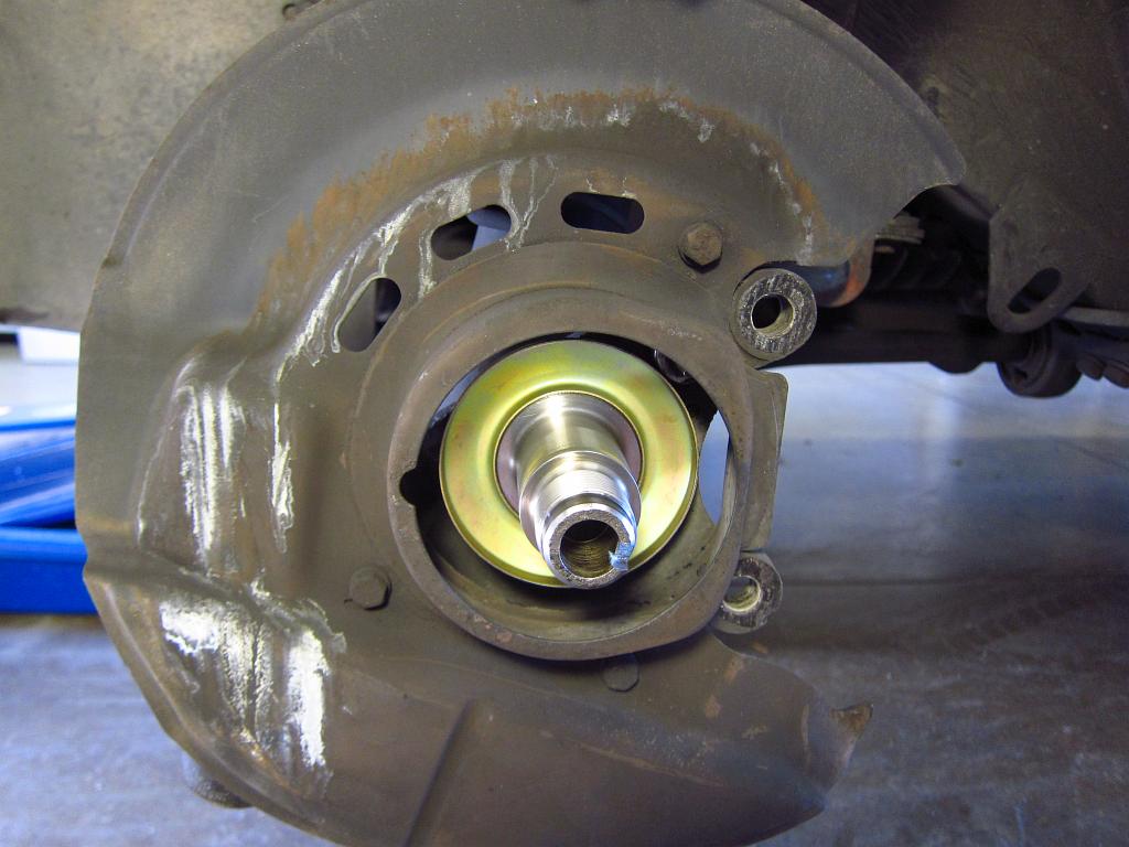
Installation of the new covers is pretty easy. You can use the old bearing assembly, the 36mm socket and a mallet to press the cover onto the axle shoulder. Make sure to leave a little grease on the axle shaft so that the bearings slide on without binding, and make SURE that they are straight so that they don't cock. The inner race can pop off, and you will be screwed if it gets stuck on the inside of the shaft. Anyway, smack it until the new cover is all the way on (flush with the end of the axle shoulder).


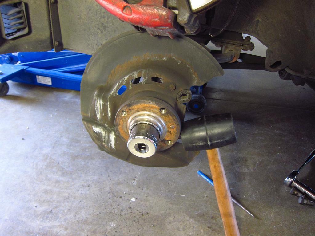
Now you can install the new bearing + hub assembly. Wipe any remaining crud off of the axle shaft and apply a tiny bit of grease to it so that the bearing will slide on easily. I had some Molykote left from a clutch job, so I used that. Installation will be super easy if the axle shaft is clean and not pitted with rust. Slide it on, and again use the 36mm socket and mallet. Do NOT push on the hub assembly or put any sort of load on anything EXCEPT the inner race. The bearing can come apart if you push on anything other than the inner race.


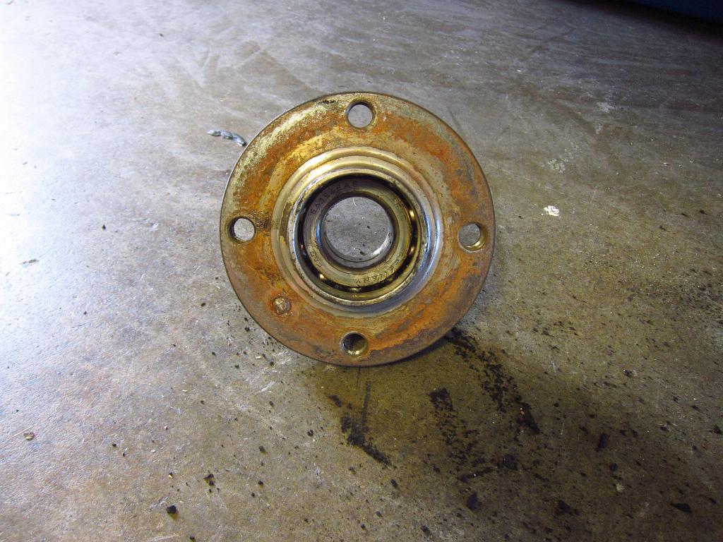
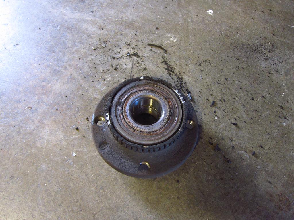
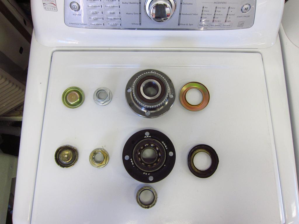
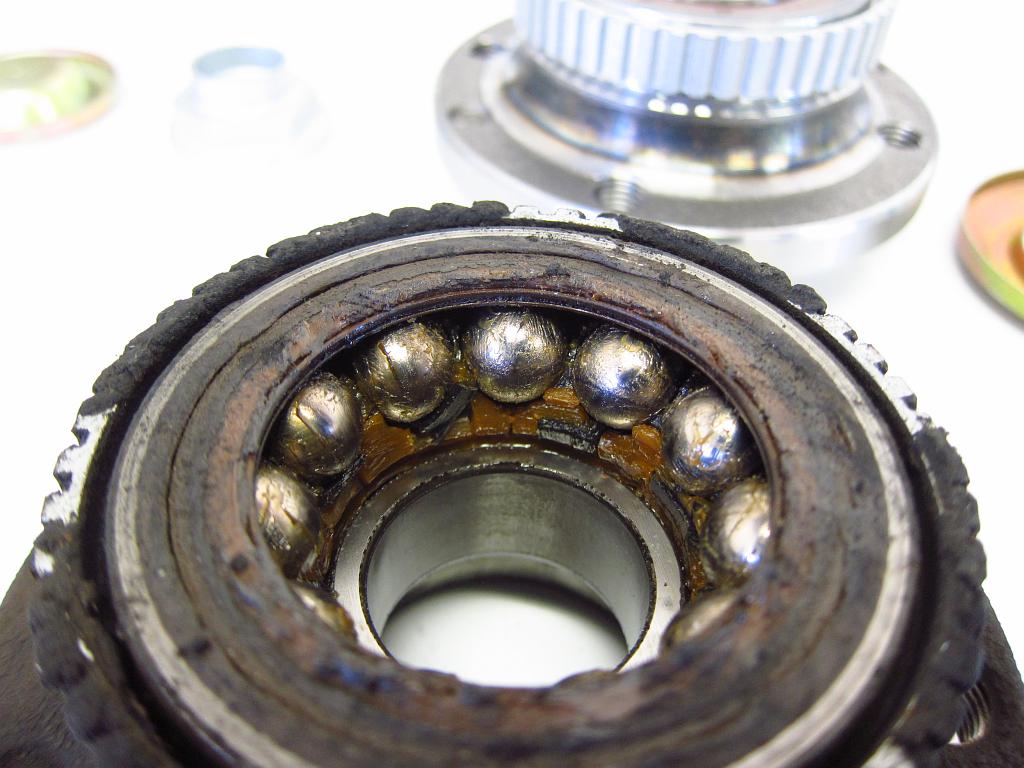
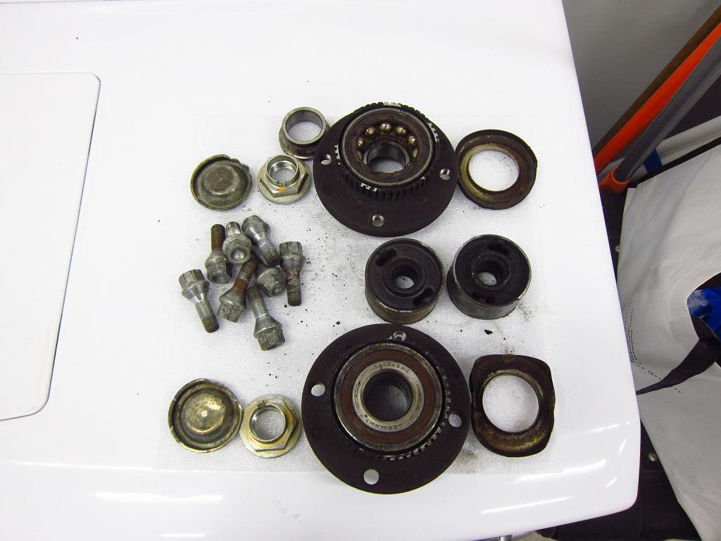
Here you can see the parts that were replaced. The old bearing was not in great shape. There was a bit of runout, and the balls' plastic inner race was totally destroyed. In fact, the inner metal race fell right off when I was removing it (but thankfully it was easy to slide off of the axle).


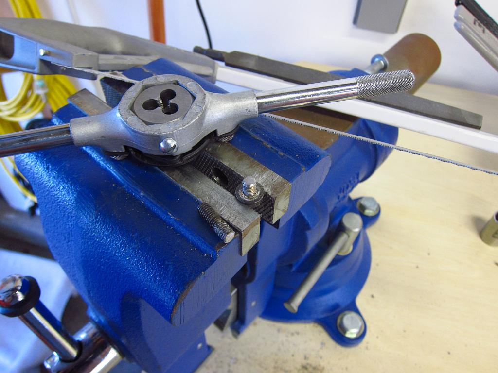
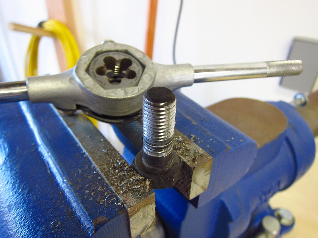
A small aside...when I was putting the passenger side stuff back on, I noticed that the rotor's dust shield was loose. At first I thought that the top M6 bolt had fallen out since it was not present, but it was actually (surprisingly!) the case that the top hole had never been tapped in the first place! I have done 3 or 4 brake jobs on this car and I can't believe that I never noticed this! So, I drilled the hole to the right diameter and tapped the needed M6x1 threads into it. As for the fastener, I have a box of spare E30 nuts and bolts, so I got an M6 one with a captive washer and chopped it down to size. Problem solved! This might explain a weird rattle/buzz that has been bugging me for quite some time lol.

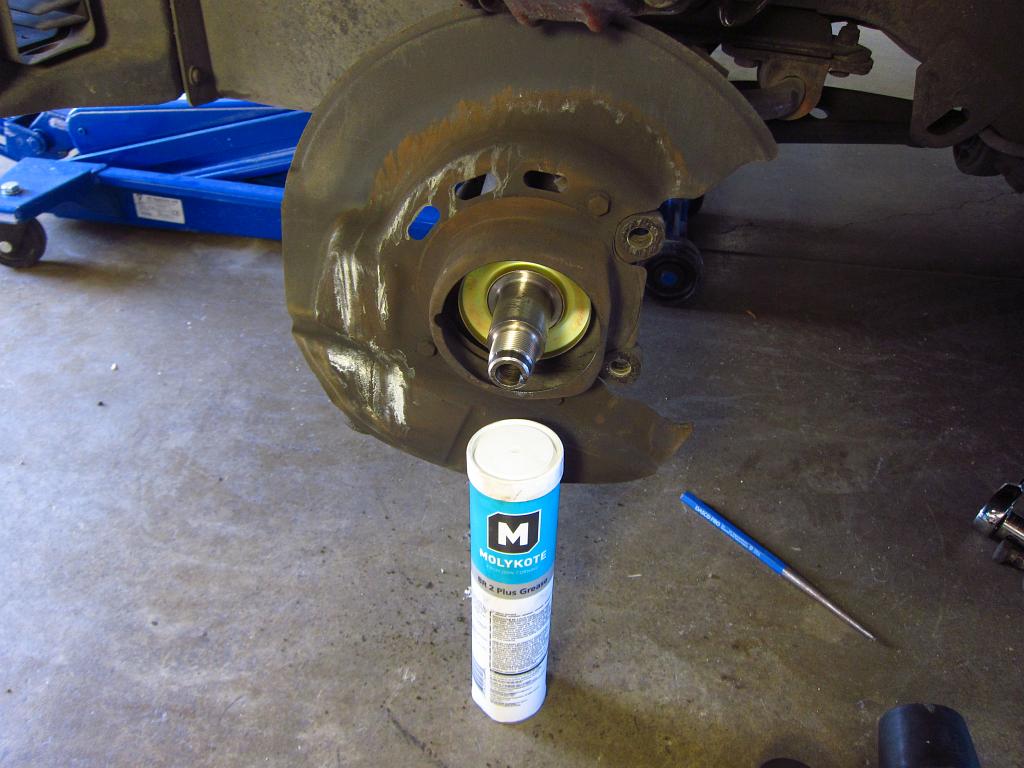
Also, at this point you should put the new axle nut in. Do not torque it down yet since you will need the wheel for support again. Just get it on there and apply enough torque to seat everything firmly (maybe 50 ft-lbs or so).


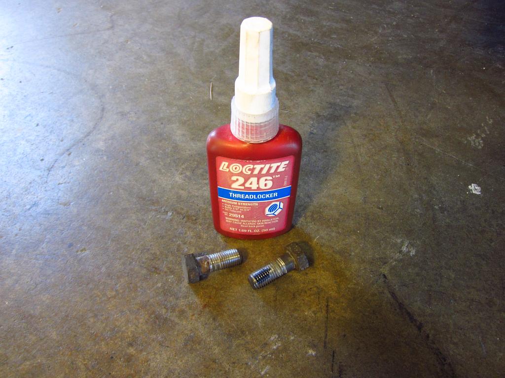
With that bit of nonsense taken care of, I cleaned up the brake carrier bolts a bit since they were full of crap. With these bolts, it is also a very good idea to use a little thread locker since they experience a lot of thermal cycling and cyclical mechanical loading.


Now you will put the wheels back on and tighten the lug bolts a bit to make sure that the wheel is seated on the hub. Lower the car so that the suspension compresses an inch or two, ensuring that the wheel will take the vertical load when you tighten the axle nut. The axle nut needs to be torqued to 210 ft-lbs. I accomplished this with an 18" breaker bar and my own 165lb weight. With my weight applied at ~15", I got around 210 ft-lbs on there, and I bounced on it a little so it probably ended up closer to 240 ft-lbs. Unfortunately, the nut is sort of shallow and it can be tricky to keep the socket on it. On one side, it did manage to slip off and bang up the nut a little, but I still got it torqued down just fine. So, just be careful when you are doing this and make sure that you don't apply any lateral force when standing on the bar.

Once the nut is on at full torque, you need to make a lock tab. I got a slightly larger punch and used it to hammer the lip on the nut into the axle's lock groove. You want a punch that is only slightly narrower than the groove so that the lip will shear as you mash it in. Just be sure to aim carefully so that you don't mess up the axle.


Finally, you need to put the on the new outer dust cap. This is pretty easy. I used a mallet and the 36mm socket again. You can also try hitting the cap's lip a little at a time in a circumferential pattern to seat it. Just don't whack the middle of it or it will just collapse in. The dust caps are SUPER important, and you need them installed properly or your new bearings will not last very long.


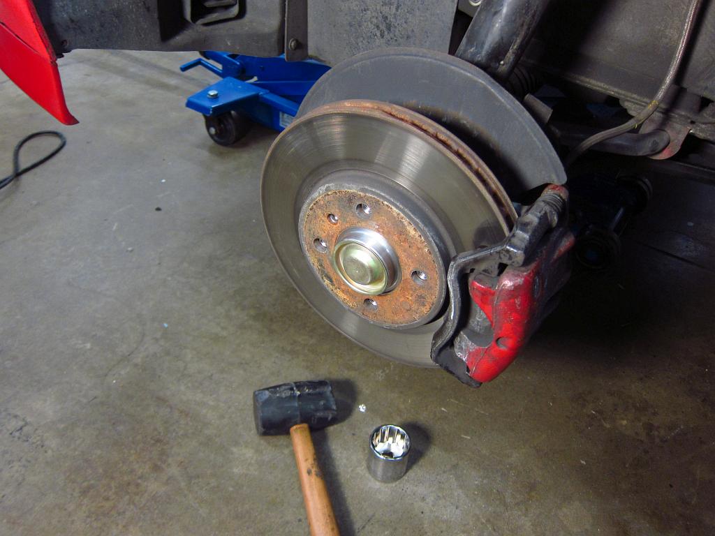
And there you have it, nice new front wheel bearings!


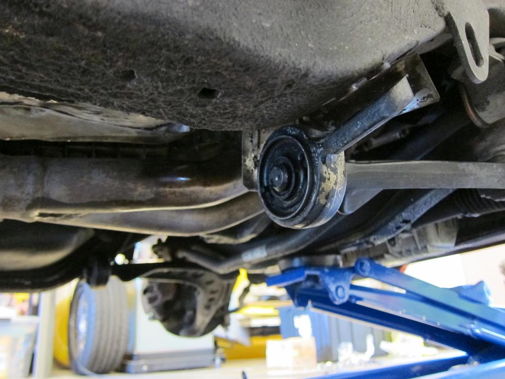
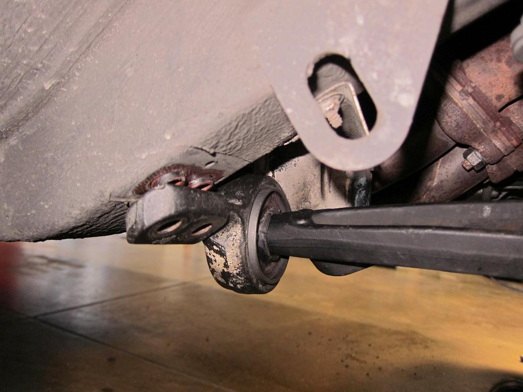
The other order of business today was to replace the front control arm bushings. Mine were almost a decade old, and while they were not torn, I had installed them in the wrong orientation (patience was not my strong suit back in college haha) and they were probably close to needing replacement anyway.

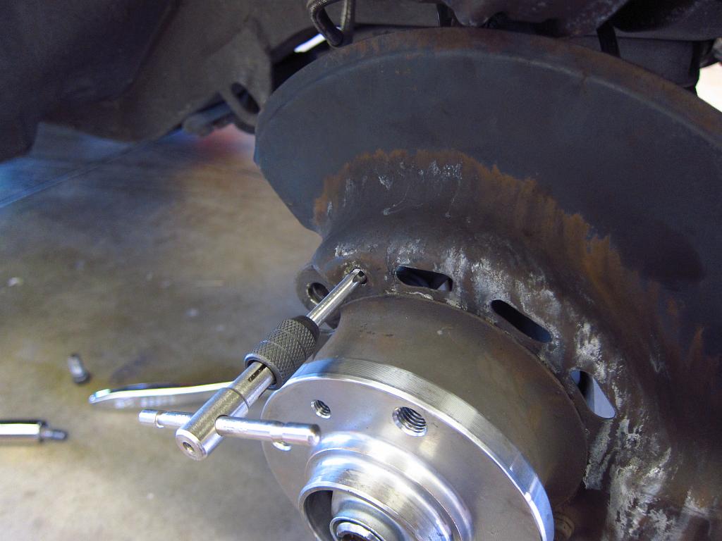
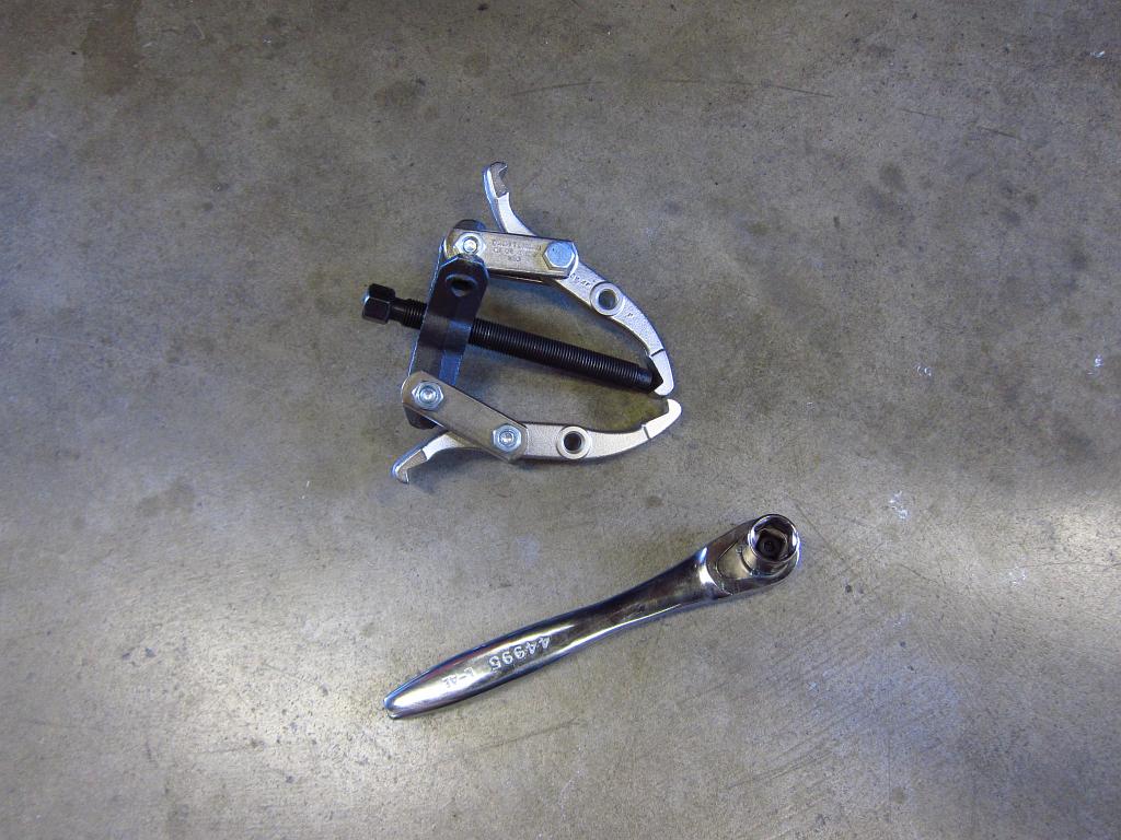
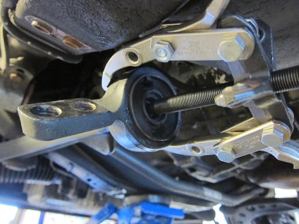
Removing them from the control arms was simple. I shot them with some PB Blaster and then used some gear pullers to get them off of the arms.


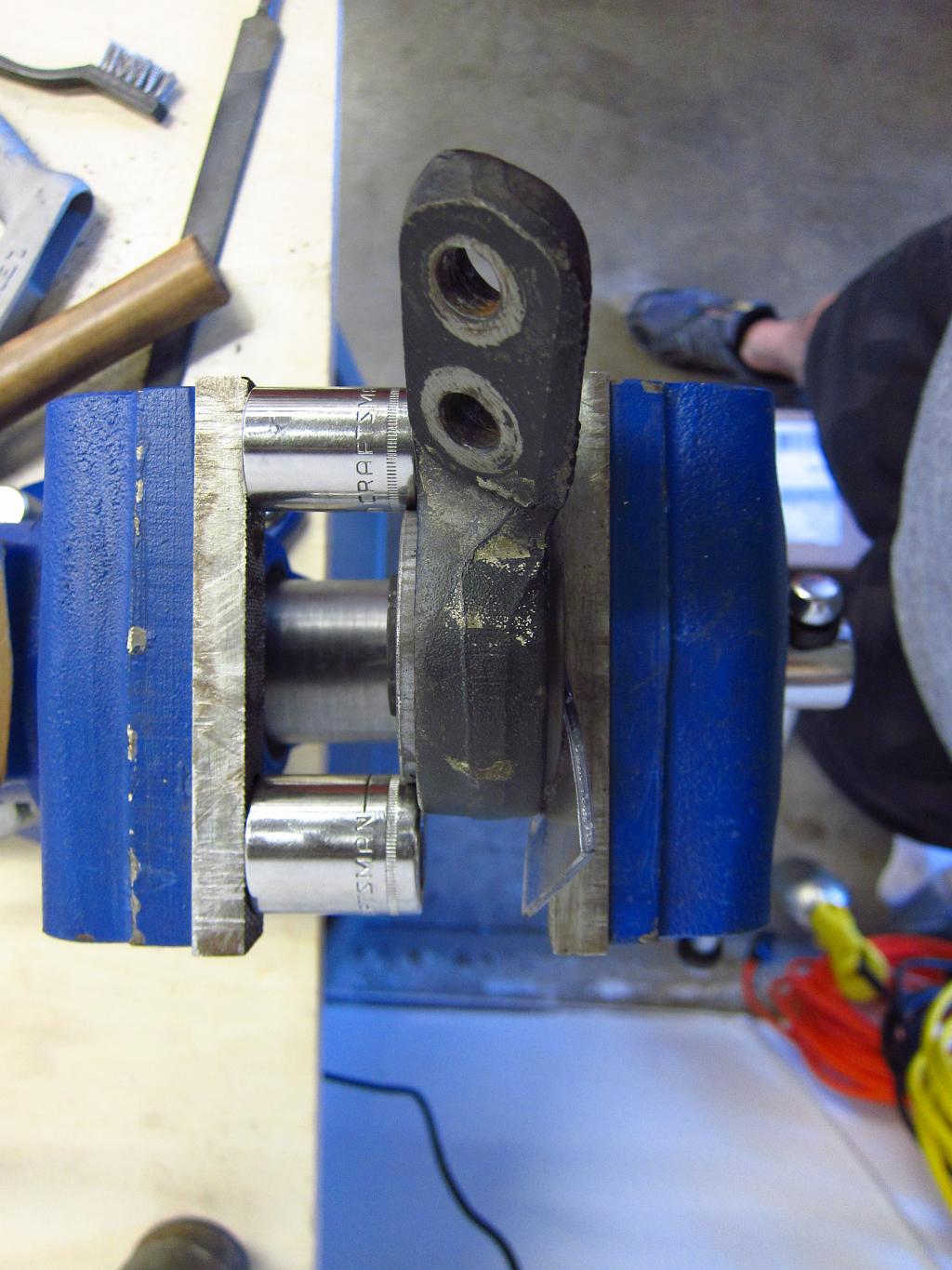
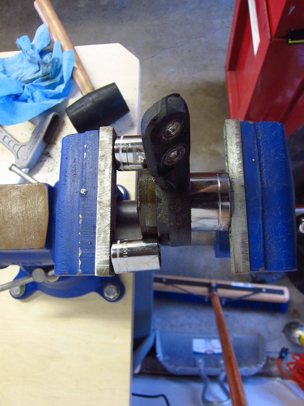
Getting the bushing out of the bracket was a little bit of a pain, but still doable with a bench vise. I hit it with some more PB Blaster and used some sockets as spacers to start pushing it out. Once it moved the first 3mm or so, I was able to stick a 1.5" (~38mm) socket in there and push on the rubber web to push the bushing out. Your results may vary here, and if you have a shredded bushing or just a standard E30 one (this was an E36 M3 bushing) the rubber might not be strong enough. Note that the 1.5" socket is still smaller than the outer metal ring and it was pushing on the rubber just inside the ring. It was the biggest socket I had on-hand, so I decided to give it a shot.


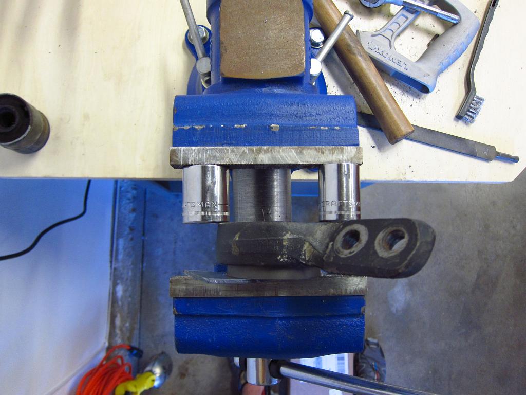
Once the bushing is out, clean out the bracket. I blasted it off with some brake cleaner to get the oil off. After that, you need to press the new bushing in. It is about as much of a pain as removing the old one. You can get the bushing in 95% of the way very easily by just sticking the bracket and bushing in the vise and paying attention to make sure that it goes in straight. Stick a piece of wood or plastic between the vise's jaw faces and the bushing so that you don't chew it up. Note that with the centered E36 M3 bushings, you will have the "holes" on the sides, and the little square nubs in them are supposed to align with the mark on the bracket.

To finish installing the bushing, just use some sockets as spacers again. Once it is pushed in enough to be evenly centered, you are done. Easy!


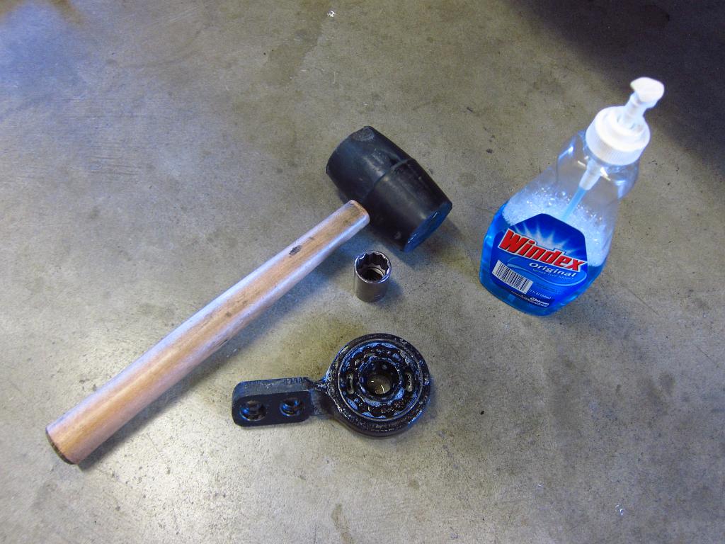
Getting the bushings onto the control arm is also VERY easy. A lot of people have trouble with this (I used to as well). Well, a little trick that I read on the forums was to use some glass cleaner on the bushing to make it slide on. This worked FLAWLESSLY. I sprayed the bushing down and was able to get it onto the control arm with 3 whacks with the mallet. From there, a 23mm socket was all I needed to get the bushing pressed the rest of the way on. The glass cleaner also made it super easy to rotate the bushing once it was on so that the bracket would be aligned with the chassis without adding any unwanted torque pre-load to the rubber.

Here's the progress after a few whacks.


And after some whacks with the socket...


And here's a nice pile of junk parts. I am particularly looking forward to having fresh front wheel bearings since at least one of them was starting to crap out.


So, that's it for today. Tomorrow I will start ripping apart the rear end. All of the related bushings and wheel bearings will get pressed by a local suspension shop though. My vise only opens 5" which is not enough for most of these, and I am pretty sure that it would break if I tried to do the diff bushing with it. I have done all of the rear bushings myself in the past using pipe fittings and threaded rod, but it was a pain in the ass and I was not able to get the subframe bushings all the way in (came up ~3mm short).
« Last Edit: March 10, 2016, 10:00:21 PM by bmwman91 »

06/05/2011 - 212,354 miles
Visit HERE for a plethora of 318iS stuff and some other randomness.  Would you say I have a, plethora, of pinatas?

bmwman91

  • Administrator
  • Legendary
  • *****
  • Thank You
  • -Receive: 33
  • Posts: 2798
    • View Profile
    • http://www.e30tuner.com/
Re: Suspension and Driveline Overhaul 2016 (Photo Log)
« Reply #1 on: February 29, 2016, 04:21:54 PM »
I made lots of progress today. The entire rear end is apart now, and I just need to unbolt a couple of odds and ends tomorrow (remove the driveshaft and front sway bar). All in all, it only took me around 3.5 hours to get everything out. This is the 3rd or 4th time I have had an E30 rear end apart, so it helped a lot knowing what was what. Also, I applied anti-seize compound to all of the bits that usually get stuck/fused back when I did the last overhaul in 2007, so it was a piece of cake to separate things.

I also found that my stainless brake lines, which I ordered from Pelican a few years ago, may not be DOT-Approved. The other thread in here which goes over what legal ones look like has some good info, and I don't know what to think since Pelican says that these lines are DOT-Approved in the product title, but they lack the features that make them so. Anyway, brakes are what keep me alive, so I ordered a new set from Ireland Engineering since those are known to be reputable and have DOT approval.

So, without further ado, here are some pictures of today's activities. I began by loosening the rear axle bolts. Obviously this is most easily done with the wheels on the car and on the ground. To get at the bolt, you need to get the locking plate out. It is pretty easy. Once again, a hammer, sharp punch, flat blade screwdriver and some needle nosed pliers are all you need. Take care not to bang up the hub when bending the lock plate away from it. Once you have it bent in a little, you can grab the lip with the pliers and wiggle it out pretty easily.


With the lock plate out, you can now get the axle nut off ( :P :-X). You will need a 30mm socket and breaker bar. The torque spec is 145 ft-lbs so you will probably need to stand on the breaker bar to break things loose. Again, just break the 30mm loose, but don’t do much more than that until you jack the wheels up off of the ground.


Now you can jack it up and put it on stands. Supporting it under the subframe is obviously not part of the plan since the subframe is coming out, so you will need to use the unibody. On the passenger side, my stands would end up mashing into the gas tank if I used the hardened factory support points, so I moved the stand an inch or so forward to clear the tank. I like to fold up a rag and put it between the stand and car so that things don’t get scraped or mashed up.


Take the wheels off and start disconnecting shit. Unplug the speedo sensor (easy one to forget!), unbolt the sway bar links and unbolt the shocks. When doing the shocks, support the hub with a jack so that it does not slam down (the shock holds the rear springs under tension).


Next you will want to take the brake calipers off. Unbolt the two 17mm bolts that hold the caliper carrier to the hub and put the caliper assembly up out of the way so that the hose is not under tension. Take the brake disc screw out and pull the brake disc off (remember to disengage the e-brake!). Once the disc is off, you will have to disconnect the E-brake cable. Start by taking off the two tension springs that hold the brake shoes together. Needle nosed pliers are all you need. Note that there are two springs, and they are different. The straight one (shown in photo) goes on top, and the offset one goes on the bottom with the straight wire on the bottom to clear the hub.


The next part is a bit of a pain sometimes. You need to disconnect the E-brake cable from the yoke. You can do this by rotating the yoke assembly open and pushing the little pin out. I took some pictures of this after it had been removed since things are very tight between the hub and dust shield. You can see how things are put together, and it is not too hard to separate them in the small space provided behind the hub.


Next, unplug the brake pad wear sensor and the ABS sensors, and stick them up out of the way.


The next few steps can be done a couple of ways. Some people like to drop the entire rear end out as one piece (subframe, differential and trailing arms). I have done it that way, and it is sort of a hassle when you are working alone because it is hard to balance the assembly on the jack when trying to lower it. So, this time around I decided to remove things one at a time and it was very easy (again, probably because I used anti-seize compound on things and generally kept fasteners clean when I did this overhaul 9 years ago). Your results will vary depending on the condition of things, and if you have helpers it might be best to drop it all out as one. There are still a few things to be done though, such as disconnecting the brake hydraulics, unbolting the driveshaft and unbolting the 3 main connection points of the rear suspension (2 subframe bolts and 1 diff bolt). Since I did things one at a time, I will detail the steps involved in that process.

So, I began by removing the axle half-shafts. It was pretty easy. Leaving the car in neutral to allow things to rotate made it easy to get a good angle on everything, and a whack with the mallet had the socket cap screws loosened right quick. Once the 6 screws were out, it was just a matter of pushing the splined shaft out of the wheel hub. A long punch and hammer had it out pretty quick. Normally I would use pullers, but since I am replacing these (and the wheel bearings) I was not concerned about banging on things.


The shafts were generally in OK shape, but the boots had major cracks forming and there was a little runout in the u-joints.


With that out of the way, the next step was to unbolt the driveshaft from the diff. I shot the nuts with some PB Blaster, had a cup of coffee, and then came back to attend to them. You can put the transmission into first gear which should hold things while you loosen two of the nuts. Then put it into neutral to rotate it 180 degrees, stick it in first gear and remove the last 2 nuts.


Stick a jack under the middle of the diff and support it. Now you will remove the four 19mm bolts above it. They are pretty easy to get at with a combination wrench. Also remove the big nut and bolt that hold the diff mount/cover to the chassis.


Now it is almost time to drop the diff. The driveshaft may be stuck to the input flange, which is easy to fix with some gentle prying with a screwdriver. Once it is separated, you can lower the diff out, being careful to make sure that it does not catch on the driveshaft as it separates.


Now you should disconnect the hydraulic soft-lines that connect the chassis to the trailing arms. Make sure to seal them off. I like to use a zip tie and nitrile glove. This will both prevent a mess, and keep the system from draining out and filling with air (you do NOT want air to get up into the ABS unit…it is an expensive PITA to deal with).


Up next was the removal of the trailing arms. The driver’s side is pretty straightforward. A 19mm combo wrench and 19mm socket are all you really need. Again, I hit things with PB Blaster and went and had a cup of coffee while it worked its magic. Then I returned, loosened the nuts and slid the bolts out. As long as the bolts were installed from the inside, this works.


The passenger’s side is a little more involved (just a little). The gas filler hose blocks the outside bolt from coming out.


So, take the bracket and 22mm nut off of the subframe on both sides! Support things on the passenger side with the jack, lower it a little and the bolt will slide right out.


Unbolt the exhaust support bracket from the subframe.


Now comes the fun (read: shitty) part. You need to pound the giant knurled-head bolts out of the chassis. If you remove the cat-back exhaust, you can probably just slide the subframe down and off of the bolts. In my case, I left the exhaust in for various reasons, so I needed to pound the bolts out. Chances are that you will need to do this anyway. So, go into the car and pull up the rear seat bottom since that is where the bolts come out. Thread the 22mm nut back on and wail on it with a small sledge. Framing hammers probably won’t do much for you here. Smack away until the bolt breaks loose, and then remove it from inside.


Again, anti-seize compound for the win. It kept these suckers from fusing into the mounts and chassis. Still, the driver’s side took a hell of a beating to get loose!


 Here it is, in its dirty glory. You can wiggle it out without removing the cat-back exhaust, although the driveshaft makes it a little bit of a pain.


Anti-seize for the win! No corrosion or other BS going on here.


There was indeed some BS to be found in the mounts themselves though. They were definitely shot to hell, which explains the rear end’s squirrely tendencies and the loud CLUNK I got from the rear end from time to time.


To finish the day, I pulled the rear sway bar out since I will be replacing it with a 14.5mm M-Tech OEM one. This ST bar is too stiff for what I do with the car. Unfortunately, getting the bar in and out is a bit of a pain due to the Turner Motorsport reinforcement brackets that bolt in through the trunk. It added an extra 20 minutes to what would normally be a 5 minute job. BUT, these suckers do serve a good purpose, and considering I had a chassis mount point rip out with this rear bar, they are worth the hassle.


So, that’s it for today. I just need to pull the driveshaft and front way bar, which should take 30 minutes. The new suspension bushings, diff bushing and wheel bearings are going to get pressed by a shop this week as well. Once I have those items, some OEM sways and DOT-approved brake lines I will put it all back together.
« Last Edit: March 10, 2016, 10:01:21 PM by bmwman91 »

06/05/2011 - 212,354 miles
Visit HERE for a plethora of 318iS stuff and some other randomness.  Would you say I have a, plethora, of pinatas?

bmwman91

  • Administrator
  • Legendary
  • *****
  • Thank You
  • -Receive: 33
  • Posts: 2798
    • View Profile
    • http://www.e30tuner.com/
Re: Suspension and Driveline Overhaul 2016 (Photo Log)
« Reply #2 on: February 29, 2016, 04:23:36 PM »
Alrighty, I dropped the rear subframe, trailing arms and medium-case diff cover off at a shop this morning. I should have my parts back with new bushings and bearings in a couple of days. This car should feel like new with nice fresh rubber in the back!  ;) :o ::)

06/05/2011 - 212,354 miles
Visit HERE for a plethora of 318iS stuff and some other randomness.  Would you say I have a, plethora, of pinatas?

Darky

  • Hero Member
  • *****
  • Thank You
  • -Receive: 23
  • Posts: 630
    • View Profile
Re: Suspension and Driveline Overhaul 2016 (Photo Log)
« Reply #3 on: March 01, 2016, 11:45:17 PM »
Nice, love the way you used the vice!

bmwman91

  • Administrator
  • Legendary
  • *****
  • Thank You
  • -Receive: 33
  • Posts: 2798
    • View Profile
    • http://www.e30tuner.com/
Re: Suspension and Driveline Overhaul 2016 (Photo Log)
« Reply #4 on: March 02, 2016, 12:17:17 AM »
Thanks! A good vise is worth its weight in...iron?

06/05/2011 - 212,354 miles
Visit HERE for a plethora of 318iS stuff and some other randomness.  Would you say I have a, plethora, of pinatas?

bmwman91

  • Administrator
  • Legendary
  • *****
  • Thank You
  • -Receive: 33
  • Posts: 2798
    • View Profile
    • http://www.e30tuner.com/
Re: Suspension and Driveline Overhaul 2016 (Photo Log)
« Reply #5 on: March 04, 2016, 05:38:11 PM »
Alrighty, I got all the stuff back from the shop this afternoon. All new rear bushings and mounts, and some new wheel bearings. Apparently the bearings are a real pain in the ass, particularly with the trailing arms off of the car. It sounds like using pullers with the TA's on the car is easier than using a press with the TA's off of the car. They didn't have any of the BMW special tools though, so I guess it's fair enough in that case. A lot of the shops I called didn't seem to have the E30 specialty tools anymore, and I wasn't about to pay dealer labor rates to have it done there!

I also met up with another local E30'er and swapped sway bars. It looks like all of my ducks are now in a row, and now I just need to put everything back on the car! The stock sways will be interesting...I have not driven an E30 with stock bars since 2001!

Tonight's plans include reinstalling the sway bars, removing the driveshaft and swapping the brake lines (since the ones in there are apparently not DOT approved). I'll see about taking (way too many) more pictures as I do things lol.

06/05/2011 - 212,354 miles
Visit HERE for a plethora of 318iS stuff and some other randomness.  Would you say I have a, plethora, of pinatas?

keflaman

  • Administrator
  • Hero Member
  • *****
  • Thank You
  • -Receive: 35
  • Posts: 929
    • View Profile
Re: Suspension and Driveline Overhaul 2016 (Photo Log)
« Reply #6 on: March 04, 2016, 08:43:15 PM »
There was indeed some BS to be found in the mounts themselves though. They were definitely shot to hell, which explains the rear end’s squirrely tendencies and the loud CLUNK I got from the rear end from time to time.


I've had the same tendencies you describe over the past few months. I found some worn components in the front that I replaced and it helped, but didn't completely cure. I'm going to have to take a look at my subframe bushings. I'd be surprised because there's only about 20K miles on them.

Thanks for the write-up. It's nice to read fresh material with pictures that work!

bmwman91

  • Administrator
  • Legendary
  • *****
  • Thank You
  • -Receive: 33
  • Posts: 2798
    • View Profile
    • http://www.e30tuner.com/
Re: Suspension and Driveline Overhaul 2016 (Photo Log)
« Reply #7 on: March 05, 2016, 12:18:10 AM »
I would be a little surprised if the rear subframe mounts were bad after only 20k miles. How are your shocks (brand/type/miles)?

Just for fun I am going to take the old bushings (the shop gave me all of the old parts back) and cut them into cross-sections to see just how failed these bushings were.

06/05/2011 - 212,354 miles
Visit HERE for a plethora of 318iS stuff and some other randomness.  Would you say I have a, plethora, of pinatas?

bmwman91

  • Administrator
  • Legendary
  • *****
  • Thank You
  • -Receive: 33
  • Posts: 2798
    • View Profile
    • http://www.e30tuner.com/
Re: Suspension and Driveline Overhaul 2016 (Photo Log)
« Reply #8 on: March 05, 2016, 02:00:56 AM »
Nightly update...

One thing I didn't get pictures of was the removal of the front sway bar. It takes all of 5 minutes. Just unbolt the end links from the control arms, unbolt the bushing shells from the chassis, unbolt the control arm lollipop on one side and slide the bar out. No hassles there.

I took care of a few odds and ends this evening. To start, I unbolted the driveshaft from the transmission. This is pretty easy to do. Just stick the transmission into neutral so that the shaft will spin freely, and take off the three 17mm nuts and bolts that hold the guibo to the tranny's output flange. A combo wrench and socket will make short work of this. There's an important detail to note in here, particularly if you plan to replace the guibo. See those little triangular bumps on the outside of the guibo? They are supposed to point to at the flange that they connect to, not a bolt head (so in this case, it is installed properly). To be honest, I have no idea what difference this makes, but the shop manual says to pay attention to it.


Here it is, ready to be removed. Super duper easy.


The next order of business is getting at the center support bearing. Pulling the heat shield is necessary here. In the case of my car (M42 engine with gen II Supersprint cat-back with no resonator) I didn't need to pull the exhaust to get it out, but it did take a couple of minutes worth of shimmying.


Loosen the two 13mm bolts that hold the CSB and slide everything out.


When you pull an E30 driveshaft, remember that the two halves are balanced as a unit, and you need to keep them in the same orientation that they were balanced in. There are little white paint marks that indicate the alignment. In a lot of cases they will be obscured by dirt, but they should be there. The first time I pulled a driveshaft (like 15 years ago) I had no idea about any of this and put it back together out of alignment. BIG mistake. The car felt like it was going to rip itself apart by 35MPH.


So here things are, unbolted and I the new guibo, which will go on a new(ly refurbished) driveshaft.


So, with the driveshaft out, I turned to the parking brake cables. First up was the easy part. Take the rear center console out (one plastic 10mm nut under the ash tray). Then remove the 10mm nuts that hold the cable ends in the lever. Also observe where the cable tubes come up into the cabin. You will want to move the cables so that they can be pulled straight through from under the car.


The next part seems to be the one that causes much consternation in people that try to replace these. I have read all sorts accounts of how people get these out, and a lot of them seem to involve a torch. I was not about to go that route since the brake lines are directly adjacent to these suckers, as well as a 25 year old gas tank and hoses. I soaked the joints in PB Blaster for 2 days (which I found did exactly nothing after the fact) and ultimately broke them free with vise grips. I clamped them down really hard on the ends of the ferrules and twisted hard. I was a little worried that the tubes were going to break free, but the ferrules gave out first and came right out without any drama.


And this is where I ended the evening...old parking brake cables out of the car, with only minimal difficulty.


Tomorrow the big reassembly adventure starts!

06/05/2011 - 212,354 miles
Visit HERE for a plethora of 318iS stuff and some other randomness.  Would you say I have a, plethora, of pinatas?

bmwman91

  • Administrator
  • Legendary
  • *****
  • Thank You
  • -Receive: 33
  • Posts: 2798
    • View Profile
    • http://www.e30tuner.com/
Re: Suspension and Driveline Overhaul 2016 (Photo Log)
« Reply #9 on: March 06, 2016, 02:58:54 AM »
Daily update time. I got a lot done, and hopefully I will have it all buttoned up tomorrow. Most of the big stuff in installed now, and the differential is the only big item remaining. The rest is odds and ends.

The first order of business this morning was to swap out the brake lines for DOT approved ones. An 11mm flare nut wrench is essential here because the nuts on the hard lines is soft and you WILL strip it if you use a regular combination wrench. For some reason, probably because a lot of these lines are made in the USA, a 9/16" wrench seems to fit a lot better than a 14mm one. I also suggest using a flare nut wrench on that side, but I didn't have one of those and since these are new I was not too concerned about stripping them.


I started with the easiest ones, the fronts. Thread the ends into the calipers first, since the fittings do not spin independently of the hose, and then rotate the flare nuts in. After I finished I shot the area down with some brake cleaner.


The rear upper lines were next. These are soooooooo much easier to do with the subframe out of the car. I pre-emptively sealed the ends before installing them to try to minimize the mess. I hate brake fluid...it is messy shit and it always manages to make a big mess.


The rear caliper lines were also super easy to do, especially with the trailing arms off of the car. Same deal as the fronts...screw them into the calipers and then screw the flare nuts into them.


Here are the old, non-DOT-approved ones. I think that I got them from Pelican a few years ago.


Next up was the installation of new parking brake cables. These have plastic ferrules, as opposed to metal like the old ones. Despite this, I still coated them with anti-seize compound before installation.


The rear sway bar went in next. New end links were a very tight fit, so some Windex, a socket and a mallet were brought back into action. After that, I lubed the inside of the rubber chassis bushings with a little bit of silicone and installed the bar.


My next step was to install the rebuilt driveshaft. For this, I removed the exhaust since it was in the way. In hindsight, I should have done this later since it made installing the subframe a little more of a pain. No big deal though. Also, make sure to bias the CSB forward by ~5mm and then tighten it into place. This creates a necessary pre-load in the CSB's rubber web.

So, with the driveshaft in, it was time to install the subframe. As per usual, I applied anti-seize to the aluminum posts that mate into the chassis, and I coated the long knurled bolt too since that is contacting the aluminum post (dissimilar metals + salty/dirty water = recipe for galvanic corrosion issues). Installation was pretty straightforward, BUT, I did forget that the passenger's side trailing arm bolt would interfere with the gas filler hose so I had to drop it back down a few inches to install that.


Although I was planning to do this later, I decided to install the new half-shafts (or at least see if i was going to have to deal with pressing the splined end in since the old ones had to be hammered out). Thankfully, they slid right in by hand with no nonsense. The axle nuts are hand-tight for now, and I will fully torque them after the differential is back in the car. Lock plates will then be installed. Also, note that the procedure calls for you to lubricate the axle nuts to achieve the proper load on the shaft end. I spread a little bit of grease on the nut flange before threading them on. And yeah, I know, you generally want to avoid having the half-shafts hang on the joints. It's only temporary and the boots are brand-spanking-new so it's fine.


Here's a very important tip to remember. Do not tighten the bolts that secure the trailing arms to the subframe while the trailing arms are extended down. You need to elevate them to the regular ride height position and THEN tighten them. This is because the center metal tube is going to be locked to the subframe when you tighten the bolts, and you want the rubber to be free of torque when the arms are at their normal neutral position. I used a jack to lift the arms to the normal ride height position (jacked them until the car started to lift off of the stand) and the torqued things down. This is a bit of a pain in the ass since you have limited room to work with a 19mm wrench and socket, but it is perfectly doable.


Here's where things are at now. It should all get buttoned up tomorrow.

06/05/2011 - 212,354 miles
Visit HERE for a plethora of 318iS stuff and some other randomness.  Would you say I have a, plethora, of pinatas?

bmwman91

  • Administrator
  • Legendary
  • *****
  • Thank You
  • -Receive: 33
  • Posts: 2798
    • View Profile
    • http://www.e30tuner.com/
Re: Suspension and Driveline Overhaul 2016 (Photo Log)
« Reply #10 on: March 06, 2016, 10:49:02 PM »
Another daily update. The car still needs a bit of work before I can drive it. The plan was to finish today, but a couple of hiccups during reassembly made things run a bit more slowly than expected. The stuff that I still need to do:
- Torque the diff cover-to-chassis mount bolt
- Torque rear axle nuts and install lock plates
- Finish adjusting parking brake cable tension and apply anti-seize to the plastic ferrule in the hub
- Reinstall exhaust and O2 sensor
- Install front sway bar
- Bleed brake system

Question for other folks: Do you use silicone lube between the sway bars and stock rubber bushings? I have read a lot of conflicting info on this.

Anyway, not many pictures today, but lots of progress. I started out by cleaning up the differential cover's gasket surfaces. The aluminum cover got some sanding with a block and 400 grit paper, and then a good scrub with some Simple Green. The diff body got some scraping and wiping with brake cleaner. As for the gasket itself, I sprayed both sides with a couple of coats of Permatex High Tack Spray A Gasket. This is my favorite stuff since it is easy to apply even, thin coats. It also holds up well against most car fluids, isn't impossible to remove if you take things apart in the future, and the gasket won't "walk" when bolting it down because the coating is pretty thin.


I scraped the gasket surfaces as well as I could, but there was still a little crap left. I did not want to sand or do anything that would send grit and debris flying because I did not want it getting into the diff gears.


While the cover was off I added the fluid. We all know how "good" gear oil smells. This stuff (Titan Sintopoid) smells a lot less terrible than any other gear oil I have used over the years.


All buttoned and sealed up.


While the gasket sealer finished curing, I got the new parking brakes set up. The little expanding shackles got a little anti-seize compound since those seem to get rusty and nasty. They are pretty easy to install, just pull the brake cable end through and pop them on.


The rest of it was fairly simple too. The shoes go on (all of them are the same, just make sure to put the bigger notch on top), and a small mirror helps a lot with getting the securing posts into place properly. Next goes the tensioner screw, and then the springs which are easily installed with some needle-nosed pliers. From there, it was just a matter of messing around with the tensioner screw and the cable nuts in the cabin. According to the shop manual, things should be adjusted so that the parking brakes are fully engaged by 8 clicks of the lever (and it should be very tight by that point), with no dragging when the brake lever is down.


After that I set about to install the differential. It is fairly easy with a jack and a small mirror to make sure that the bolt holes are lined up. I STRONGLY recommend getting the driveshaft studs into the diff's input flange at this point, rather than trying to do it later after the diff is bolted in. It can be a pain to get the studs through the holes, at least with a medium-case diff. It's a lot easier to do it when the diff is still mobile. I mention this because I did not do it this way, and I wish that I had lol.


After that I attached the half-shafts and torqued their bolts to spec. Things are really coming together now!


The big hiccup that I ran into today was that one of the threaded studs in the end of the driveshaft was not properly staked into the yoke, and it would spin when I was trying to tighten the nut on the diff side. The local hardware store didn't have anything remotely similar, so I had to improvise. I chased the stud's threads and ran a tap through the ovaled nut so that it would at least go on smoothly. Because of this I did opt to use thread locker. Anyway, I managed to get some full size vise-grips onto the stud's head and wedge them between the driveshaft and subframe so that I could apply full torque to the nut. God help me if/when I need to remove this, maybe the same trick will work then too. If not, I will just have to disconnect the driveshaft in the middle and drop the diff with it still attached.

One other, less severe, complication today was related to the front sway bar. It turned out that I didn't have all of the stock linkage parts that I needed to mount it, but I should be getting those later this week. As odd as it might sound, I am actually excited about returning to stock bars. Sure, the car will roll a little more in corners, but I figure that traction will improve a little since the inside wheels will have less force pulling them upward.
« Last Edit: March 10, 2016, 10:02:05 PM by bmwman91 »

06/05/2011 - 212,354 miles
Visit HERE for a plethora of 318iS stuff and some other randomness.  Would you say I have a, plethora, of pinatas?

Darky

  • Hero Member
  • *****
  • Thank You
  • -Receive: 23
  • Posts: 630
    • View Profile
Re: Suspension and Driveline Overhaul 2016 (Photo Log)
« Reply #11 on: March 08, 2016, 12:22:53 AM »
Hi bmwman

Nice work what's the differential centre?
It not clutch or Bmw torsen.

What where the old sway bars that you had on?

I'm also developing a theory that you and Norn are actually working on the same car.

Cheers Rohan

bmwman91

  • Administrator
  • Legendary
  • *****
  • Thank You
  • -Receive: 33
  • Posts: 2798
    • View Profile
    • http://www.e30tuner.com/
Re: Suspension and Driveline Overhaul 2016 (Photo Log)
« Reply #12 on: March 10, 2016, 02:45:37 AM »
I traded the sway bars (ST 22mm / 19mm) for some stock ones (20mm / 14.5mm) with another local E30'er.

The diff...funny you ask. What is it, indeed. It is supposed to be a Quaife helical gear diff, and I am working with another guy right now to determine if it actually is one because a few things have me questioning that. It does seem to behave like a helical gear unit, but the gears I could see inside the shell certainly do not look helical! When I did some experiments in the garage tonight, here is how it behaved:

1) Both wheels raised in air, diff input flange free, both wheels spin freely in same direction
2) One wheel on ground, diff input flange free, the raised wheel can be spun with medium resistance
3) Both wheels raised in air, diff input flange locked, wheels spin in opposite directions with high resistance
4) One wheel on ground, diff input flange locked, cannot spin the raised wheel

Once I know for sure what it is, I will certainly post it!

06/05/2011 - 212,354 miles
Visit HERE for a plethora of 318iS stuff and some other randomness.  Would you say I have a, plethora, of pinatas?

bmwman91

  • Administrator
  • Legendary
  • *****
  • Thank You
  • -Receive: 33
  • Posts: 2798
    • View Profile
    • http://www.e30tuner.com/
Re: Suspension and Driveline Overhaul 2016 (Photo Log)
« Reply #13 on: March 10, 2016, 09:09:38 PM »
So, disappointing news. The diff is just a stock 325iX viscous LSD. It seems to work, which is a plus, but it is poop in terms of performance. The gentleman that sold it to me thinking it was a Quaife unit is going to refund me (he bought an E30 with a long list of mods, including a Quaife diff, and it sounds like the seller of the car screwed him). So, I am now going to talk to a local diff builder (Wanganstyle on r3v) about a proper custom-built unit for this car so I can get rid of the iX diff ASAP! I am mostly just disappointed that it is not a Quaife since those are no longer made for the E30 diffs and they are super rare, but I am getting taken care of by the seller and now I can really put serious thought into what type of LSD I want to run.

06/05/2011 - 212,354 miles
Visit HERE for a plethora of 318iS stuff and some other randomness.  Would you say I have a, plethora, of pinatas?

Darky

  • Hero Member
  • *****
  • Thank You
  • -Receive: 23
  • Posts: 630
    • View Profile
Re: Suspension and Driveline Overhaul 2016 (Photo Log)
« Reply #14 on: March 11, 2016, 04:28:24 PM »
Hi

Why is there a performance loss on the viscous diff? It's just smother than the clutch set up. Won't quite take the load a clutch will either.

Also look at bmw torsen oem diff centres, there not quite as good as quaife as far as load goes but the they are still pretty good. Cheaper than quaife too but more expensive than the clutch set up. That's what I use.

Cheers Rohan