Author Topic: The Definnitive M42 Crank and Cam Angle Info Thread  (Read 17276 times)

bmwman91

  • Administrator
  • Legendary
  • *****
  • Thank You
  • -Receive: 33
  • Posts: 2798
    • View Profile
    • http://www.e30tuner.com/
The Definnitive M42 Crank and Cam Angle Info Thread
« on: December 18, 2015, 02:34:17 AM »
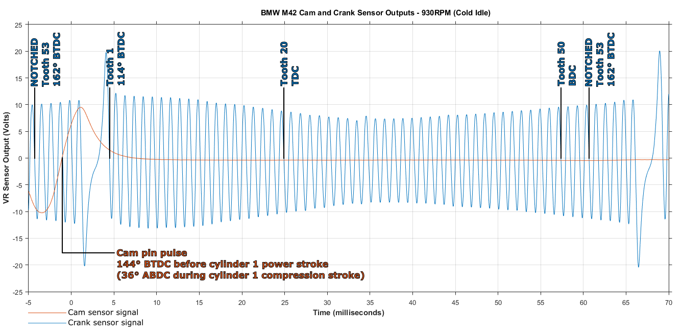
So, there is a bit of info out there regarding tooth angles and whatnot for the M42, but no single cohesive place with all of it. If you read around enough, you will probably come to the conclusion that the first tooth pulse after the gap is 114 degrees BTDC, which is correct as far as the physical setup on the engine goes. Since I am planning to rock a MS3Pro ECU at some point in the next year or two, I wanted to get a clear idea about this and document it once and for all. I borrowed an oscilloscope and popped the shell apart on the 88 pin connector that plugs into the Motronic so I could directly measure the VR sensors (and yes, both are VR type). It's been too long that only the M20 guys have had nice, well defined information to work from, and it is time for the M42 to get some nerd-love!

Which wire is which? This causes some confusion, mainly because the cam and crank sensors have the same wire colors, but one's polarity is reversed because BMW decided to swap the wires (for whatever reason). Keep in mind that this is the E30 M42, and I do not know if this changed in the E36.
- The crank sensor uses pins 67 and 68 of the Motronic. Pin 67 takes the black wire from the crank sensor, and this is the POSITIVE sensor output. Pin 68 takes the yellow wire from the crank sensor, and this connection is GROUNDED inside the Motronic. So, pin 67 is the crank sensor signal, which by convention would be called the positive output of the sensor.
- The cam sensor uses pins 16 and 44 of the Motronic. Pin 16 takes the yellow wire from the cam sensor, and this is the NEGATIVE sensor output. Pin 44 takes the black wire from the cam sensor, and this connection is GROUNDED inside the Motronic. So, pin 16 is the cam sensor signal, which by convention would be called the negative output of the sensor.

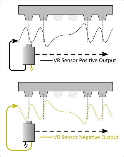
I am not sure why BMW reversed the signal wires between the two sensors. For those that are going stand-alone, you have the option of getting your cam signal from pin 44 (the positive output) and then whatever conditioner circuit you are feeding that (and the crank signal) into will behave the same way. With a VR sensor, both wires will essentially provide the same signal, but one is "flipped upside-down" relative to the other. Most VR conditioner circuits are designed for the VR positive output, and will give a digital rising edge when the VR output crosses zero from positive to negative.

The positive/negative convention is shown in the diagram below.

Great, so that is a lot of reading about VR basics. What about the M42?

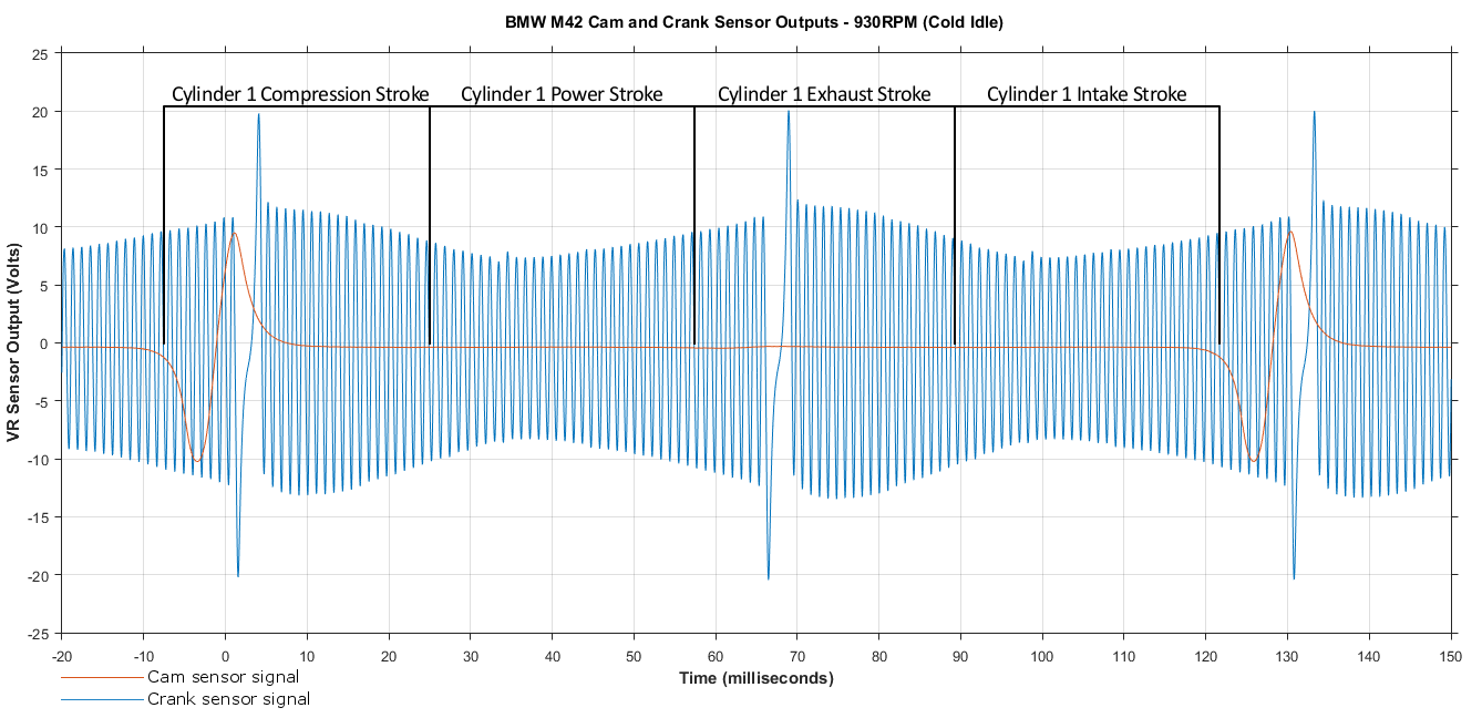
First, here's a scope shot of two full rotations of the crankshaft, with some annotations added. The amplitude changes a lot as the crank turns because my damper wheel is either out-of-round, or just worn out, so some teeth get closer to the sensor than those on the other side of the wheel. I did some measurements at 2000RPM and 3500RPM as well, and at 3500RPM the big voltage spike peaked at around 50V. That means that at redline, the VR sensor is going to be putting out a signal that peaks at over 100V.

Here it is zoomed in a bit, with the important teeth marked.

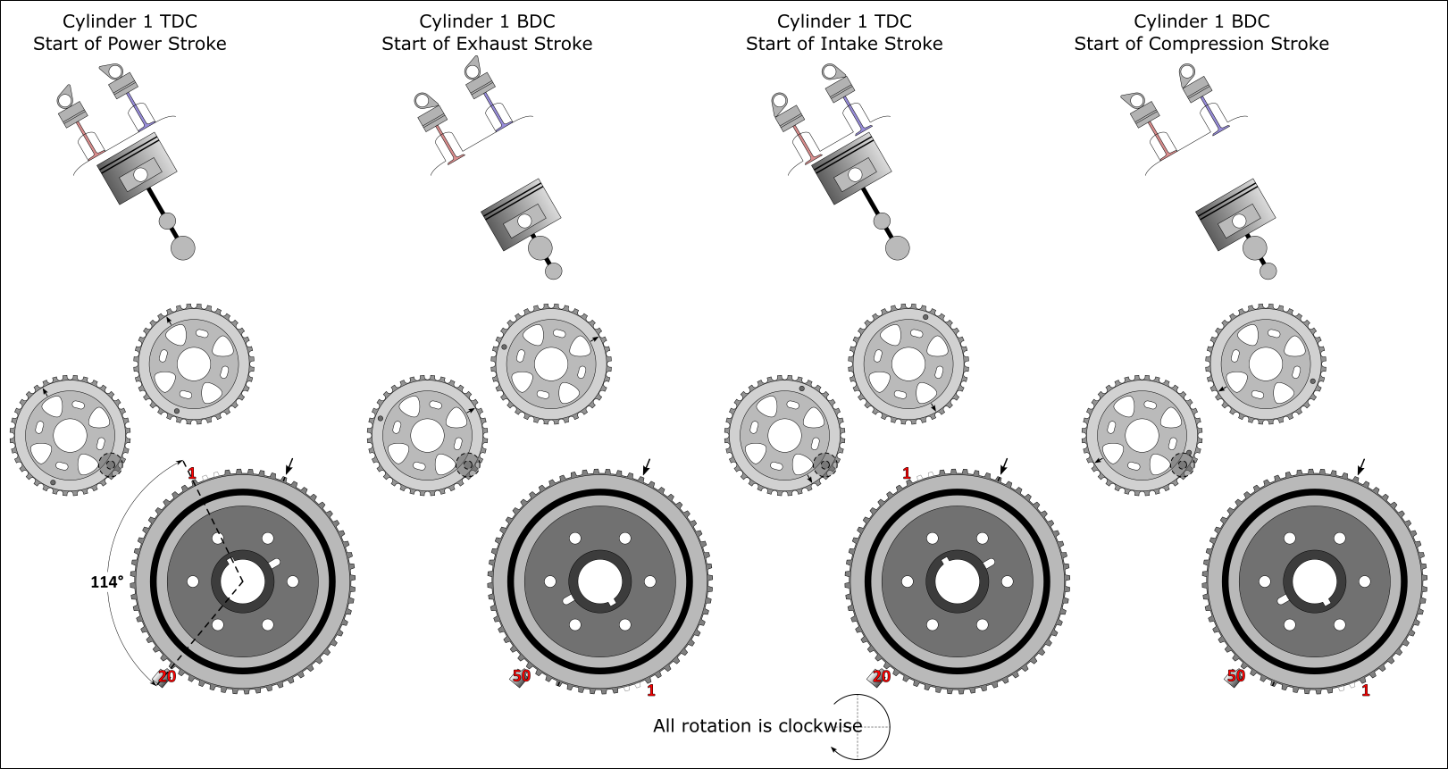
And here's a fun little graphic showing what is what and the relationship between moving parts with respect to the cam and crank sensors. Note that the cam lobes are not to scale or anything; they are just for fun to illustrate the general idea.


Note:
This is all based on photos of mine from over the years and a lot of online image searching. Thankfully it all seems to agree with existing information, as well as the oscilloscope measurements. If you find an error or think that you see an error, please let me know so that I can see if a correction is needed.


I plan to do a pretty in-depth look at ignition coil dwell times too, since that is also a critical parameter. That will involve more oscilloscope action with the goal of determining the factory dwell times for the coils (both for the M42 coils, and the M54 coils that many of us run with our COP conversion). In a year or two (or whenever I get my ass into gear and install an aftermarket ECU) I will try to document all of the factory equipment (thermistors, idle control valve, etc) so that others will not have to spend weeks and weeks scratching their heads.
« Last Edit: December 18, 2015, 08:03:50 PM by bmwman91 »

06/05/2011 - 212,354 miles
Visit HERE for a plethora of 318iS stuff and some other randomness.  Would you say I have a, plethora, of pinatas?

Darky

  • Hero Member
  • *****
  • Thank You
  • -Receive: 23
  • Posts: 630
    • View Profile
Re: The Definnitive M42 Crank and Cam Angle Info Thread
« Reply #1 on: December 18, 2015, 05:14:44 AM »
Great idea bmwman !!!

keflaman

  • Administrator
  • Hero Member
  • *****
  • Thank You
  • -Receive: 35
  • Posts: 929
    • View Profile
Re: The Definnitive M42 Crank and Cam Angle Info Thread
« Reply #2 on: December 18, 2015, 06:46:41 PM »
I love you, man!

bmwman91

  • Administrator
  • Legendary
  • *****
  • Thank You
  • -Receive: 33
  • Posts: 2798
    • View Profile
    • http://www.e30tuner.com/
Re: The Definnitive M42 Crank and Cam Angle Info Thread
« Reply #3 on: December 18, 2015, 08:12:16 PM »
*brofist bump*

I drew a little diagram to show the VR sensor polarity too...not more links to the MS manual.

06/05/2011 - 212,354 miles
Visit HERE for a plethora of 318iS stuff and some other randomness.  Would you say I have a, plethora, of pinatas?

cristimm

  • Full Member
  • ***
  • Thank You
  • -Receive: 3
  • Posts: 160
    • View Profile
Re: The Definnitive M42 Crank and Cam Angle Info Thread
« Reply #4 on: January 03, 2016, 08:59:04 AM »
Great work!

I always wanted to install a stand-alone for my M42 but like you said there is nowhere a detailed step-by-step tutorial.

Keep up the good work.

Darky

  • Hero Member
  • *****
  • Thank You
  • -Receive: 23
  • Posts: 630
    • View Profile
Re: The Definnitive M42 Crank and Cam Angle Info Thread
« Reply #5 on: February 18, 2016, 03:13:24 AM »
Hello bmwman

I thought the crank angle sensor was of a square output?
Is that graph accurate? What's with the massive spike on the crank sensor?

Thanks Rohan

bmwman91

  • Administrator
  • Legendary
  • *****
  • Thank You
  • -Receive: 33
  • Posts: 2798
    • View Profile
    • http://www.e30tuner.com/
Re: The Definnitive M42 Crank and Cam Angle Info Thread
« Reply #6 on: February 18, 2016, 07:16:54 PM »
The crank and cam sensors are variable reluctance types which output a speed-proportional sine wave. These sensors require adaptive signal conditioning which will convert them to a TTL 5V square wave. They are nice in that they can be used to detect ferrous metal movement without embedding magnets in anything (since the magnet is in the sensor itself).

You are probably thinking of Hall Effect sensors. That type puts out a square wave signal, but they won't work with our crank wheel because they usually require magnets to pass by them rather than just ferrous metal.

06/05/2011 - 212,354 miles
Visit HERE for a plethora of 318iS stuff and some other randomness.  Would you say I have a, plethora, of pinatas?

Darky

  • Hero Member
  • *****
  • Thank You
  • -Receive: 23
  • Posts: 630
    • View Profile
Re: The Definnitive M42 Crank and Cam Angle Info Thread
« Reply #7 on: February 19, 2016, 12:16:22 AM »
Ok that makes sense I red that sensors throw out a square wave, is the signal conditioner attached to the sensor itself?

I read on e30 tech almost exactly what you said but then I saw the graph and it didn't make sense!

So your taking your measurements before the conditioner, where's that?

But what's with that massive spike? 50 volts thats getting dangerous for electronics. Hate to have the conditioner die, probably just a scr.

bmwman91

  • Administrator
  • Legendary
  • *****
  • Thank You
  • -Receive: 33
  • Posts: 2798
    • View Profile
    • http://www.e30tuner.com/
Re: The Definnitive M42 Crank and Cam Angle Info Thread
« Reply #8 on: February 19, 2016, 06:40:08 PM »
The conditioner is composed of a series of components as far as I can tell from picking at my spare Motronic. It has some resistors, capacitors and diodes at the input of the VR sensor signal, and then it goes into a custom Bosch IC. So all of the conditioning circuitry is internal to the Motronic. The big voltage spike occurs after the double tooth gap and it is totally normal. It all has to do with what is moving near the VR sensor. That voltage is nothing toi worry about since the conditioner is designed for this.

Megasquirt and other ECU's were using the LM1815 IC for conditioning for a while, but now the new "best" IC is the MAX9926, which is also what I use in my data logger (the other big thread with air flow data and whatnot). There are other solutions as well, but the MAX9926 seems to be the best and mosty accurate way to get a VR signal to be a clean square wave.

06/05/2011 - 212,354 miles
Visit HERE for a plethora of 318iS stuff and some other randomness.  Would you say I have a, plethora, of pinatas?

sh123

  • Full Member
  • ***
  • Thank You
  • -Receive: 1
  • Posts: 144
  • Freshly Registered!
    • View Profile
Re: The Definnitive M42 Crank and Cam Angle Info Thread
« Reply #9 on: March 10, 2016, 05:07:43 PM »
so possibly going slightly off topic....

if I have a m44 front cover that has no sensor mount, and Im building stroker, are you saying the crank sensor should be mounted at 114degreed from tdc when cyl 1 is at tdc?

just I think  we decided to set mine at 120degree? or is it not that accurate?

Cheers

Ps im not 100% sure what Im talking about, im going off what my engine builder told me

wazzu70

  • Nasty Nick
  • Hero Member
  • *****
  • Thank You
  • -Receive: 18
  • Posts: 671
    • View Profile
Re: The Definnitive M42 Crank and Cam Angle Info Thread
« Reply #10 on: March 31, 2016, 11:24:41 PM »
This thread is awesome. Good work documenting all this.

I think I wired in my cam sensor backward too...always wondered why it did not work so I have the car calibrated in batch fire/wasted spark style.

I got similar measurements FWIW.
-Nick
91 E30 M42 with VEMS

Darky

  • Hero Member
  • *****
  • Thank You
  • -Receive: 23
  • Posts: 630
    • View Profile
Re: The Definnitive M42 Crank and Cam Angle Info Thread
« Reply #11 on: April 01, 2016, 02:06:27 AM »
Hi Sion

Your crank sensor is therefore 6 degrees retarded, not a big deal though but something to watch out for because the spark for ignition will happen a little late, cams can be adjusted easily most people leave there exhaust cam alone but advance there inlet 5 degrees forward.

Warsteiner

  • Hero Member
  • *****
  • Thank You
  • -Receive: 21
  • Posts: 576
    • View Profile
Re: The Definnitive M42 Crank and Cam Angle Info Thread
« Reply #12 on: April 01, 2016, 05:51:39 AM »
Sion,

On my MSII settings it says .... Tooth 1 Angle (deg BTDC) 114*

Darky,

Yes advancing the intake cam only will give you more HP at the top end without any loss on the bottom end. No need to retard the exhaust side when doing this.

Cheers,
~Ralph

petros30

  • Newbie
  • *
  • Thank You
  • -Receive: 0
  • Posts: 3
  • Freshly Registered!
    • View Profile
Re: The Definnitive M42 Crank and Cam Angle Info Thread
« Reply #13 on: January 29, 2017, 04:37:15 PM »
Your information is very intresting. I use a stand alone ecu Link G4+ and I do it Plug and play. I find very usefull the diagram and the image from oscilloscope. It's the second Link ecu which I install and calibrate and I have spent some month to finish the project.  8)