Alright, as promised, here are some pictures.
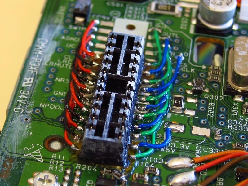
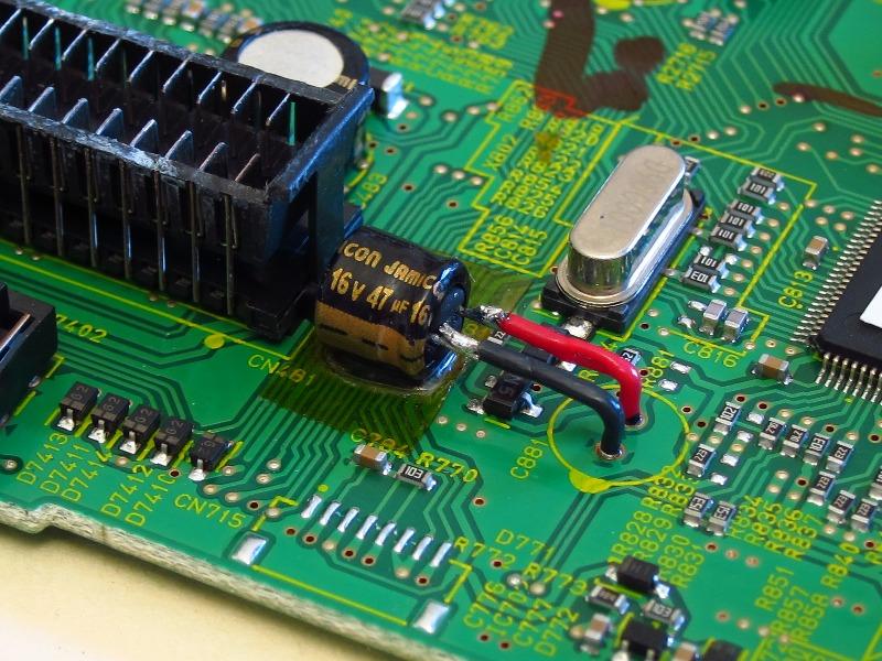
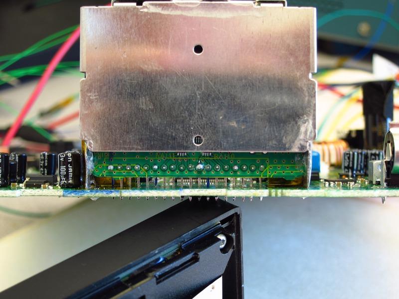
The biggest pain was figuring out how to move the board-board connector that connects the CD transport to the motherboard. I ended up lifting it and setting the ends on Kapton tape, and then filling the middle gap with super glue. From there, I ran 30ga wire from the original pads to the terminals.
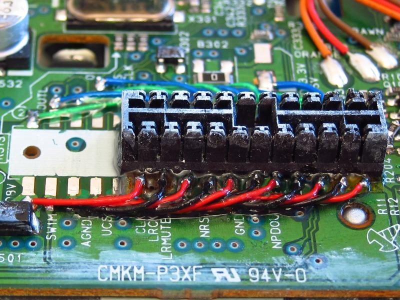
Here is another angle. Once the wires were on, I filled everything in with more super glue. The last thing I need is this sucker breaking off if/when I need to take the unit apart in the future.
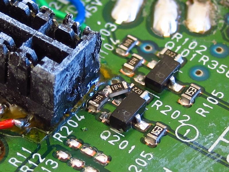
Although I had to leave a couple of components in place & buried under the connector, I was able to move this resistor out of the way, just in case I ever need to service it.
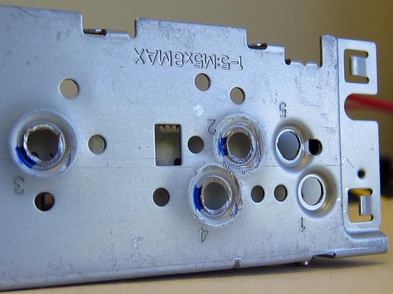
Now, to get the CD transport moved over, I needed to move its mount holes 1cm to the side. I used some calipers and a drill press to do this.
The only real mods I needed to make were to grind off an alignment post, and as seen in this picture, flatten the old stamped mounting boss. A bench vise & some aluminum blocks were all that I needed.
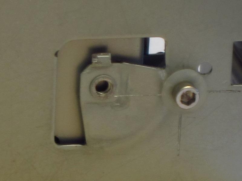
I also needed to press out some of the stamped screw holes in the side that the HD Radio module sat. The module had to be moved, and the screw bosses were interfering. Again, I used a bench vise & aluminum blocks.
This capacitor was interfering with a big one on the CD transport board, so I moved it over. It is a decoupling cap for the USB 3.3V supply. Although a setup like this isn't exactly ideal since I bet it adds some noise to the supply rail, I doubt it will be an issue. Long-term, I plan to find a big surface mount cap & replace this with that.
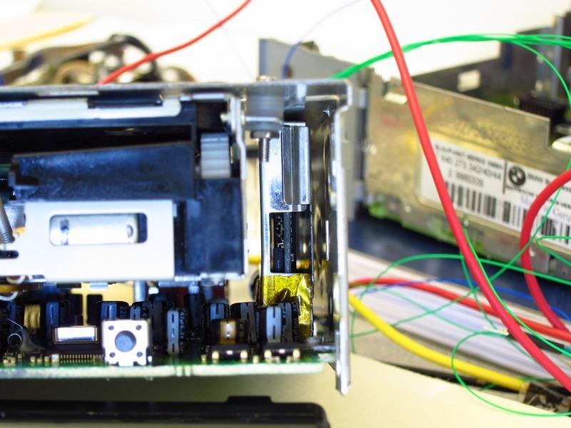
Here is the HD Radio module.I moved it as far to the side as I could. Remounting the EMI shield firmly to the board was a little tricky, and it is not quite as secure as before, but I think it will be OK.
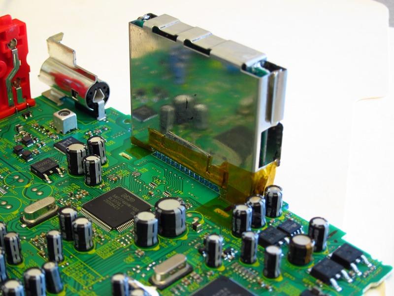
I was able to move it over by flipping the pin header at the bottom. Originally, it was mounted through the side you see in the picture. Being a simple single-row through-hole header, it was a simple matter of de-soldering it from the RF board & mounting it on the opposing side.
It all worked out perfectly!
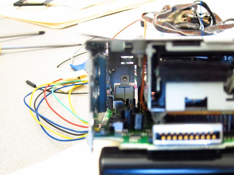
This also leaves ample room on the other side for my control circuitry. I don't think that there will (physically) be too much stuff to jam in there, but there will need to be room for a small PCB with the microcontroller & various control / power electronics.
I tested the JVC HU and the CD player + HD radio seem to be working fine. Phew!
I have been on vacation in Hong Kong / SE China for the last couple of weeks and have been using some of m down-time to work out various aspects of the microcontroller code. It is going to be a LOT of work, but that's the fun part anyway!
 Topic: The "CD43 Face on a JVC HU" Thread - Work in Progress (Read 9858 times)